Line-of-sight link directional antenna deviation correction method based on unmanned aerial vehicle location prediction

A directional antenna and UAV technology, applied in the direction of control using feedback, can solve problems such as the position of the airborne directional antenna and the installation position deviation of the inertial navigation equipment

Inactive Publication Date: 2017-01-18
CHINESE AERONAUTICAL RADIO ELECTRONICS RES INST
View PDF5 Cites 18 Cited by
  • Summary
  • Abstract
  • Description
  • Claims
  • Application Information

AI Technical Summary

Problems solved by technology

[0004] In order to improve the hysteresis of the line-of-sight link directional antenna of the ground link terminal in the digital guidance process, and solve the problems of the installation position deviation between the airborne directional antenna position and the inertial navigation equipment, the present invention proposes an unmanned Directional Antenna Correction Method for Line-of-Sight Link Based on Aircraft Position Prediction

Method used


Image

  • Line-of-sight link directional antenna deviation correction method based on unmanned aerial vehicle location prediction
  • Line-of-sight link directional antenna deviation correction method based on unmanned aerial vehicle location prediction
  • Line-of-sight link directional antenna deviation correction method based on unmanned aerial vehicle location prediction

Examples


Embodiment Construction

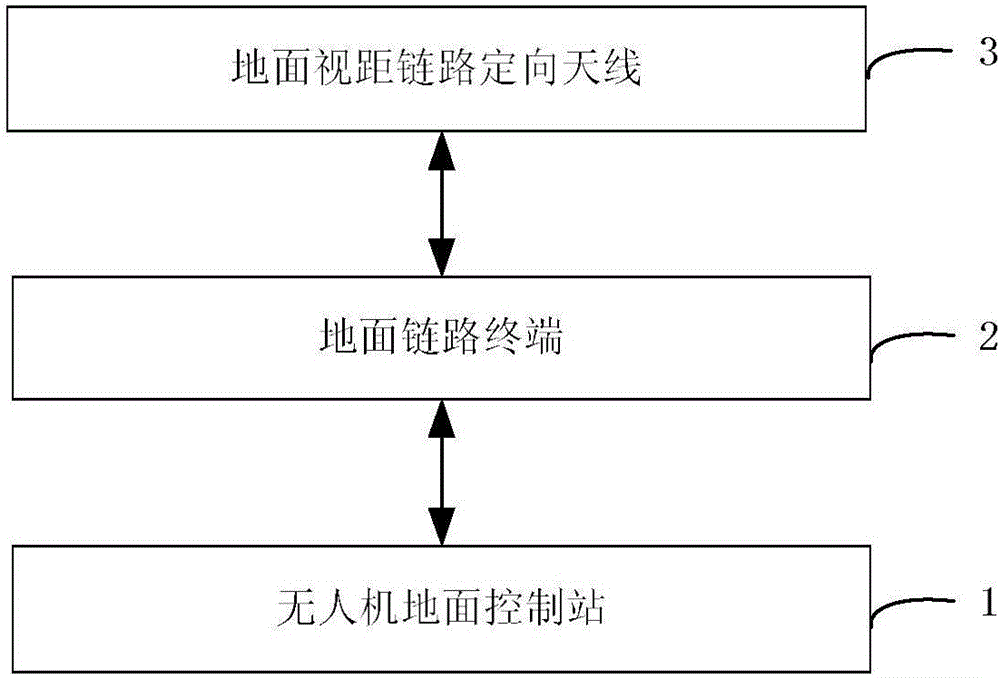
[0031] In order to improve the hysteresis of the directional antenna of the ground link terminal in the digital guidance process and solve the problems of the installation position deviation between the airborne directional antenna position and the inertial navigation equipment, the present invention proposes a UAV position prediction and antenna deviation correction Implementation. The UAV ground control station designed by this method controls the directional antenna of the ground line-of-sight link to track the UAV in the digital guidance mode, which has the characteristics of high reliability, high precision, and convenient engineering implementation.

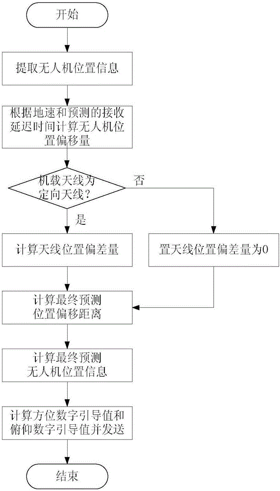
[0032] Such as figure 2 As shown, in order to achieve the above object, the present invention adopts following technical scheme, comprises the following steps:

[0033] Step a) Extract the location information of the drone from the telemetry data downloaded from the received drone: longitude λ p , latitude L p , height ...


PUM


Abstract

The invention discloses a line-of-sight link directional antenna deviation correction method based on unmanned aerial vehicle location prediction. The method comprises the following steps that a) unmanned aerial vehicle location information is extracted from the received telemeasuring data downloaded by an unmanned aerial vehicle; b) the location deviation of the unmanned aerial vehicle is calculated; c) the location offset is calculated; d) the final prediction location deviation distance is obtained according to the location deviation and the location offset; e) the finally predicted location information of the unmanned aerial vehicle is calculated according to the final prediction location deviation distance and the longitude, the latitude, the track angle or course angle and the pitch angle in the received telemeasuring data downloaded by the unmanned aerial vehicle; and f) a terrestrial line-of-sight link directional antenna is driven to rotate to the corresponding azimuth and pitch location according to the finally predicted location information of the unmanned aerial vehicle. The line-of-sight link directional antenna deviation correction method based on unmanned aerial vehicle location prediction has the characteristics of being high in reliability, high in precision and convenient in project implementation.

Description

technical field [0001] The invention belongs to the field of unmanned aerial vehicle measurement and control and information transmission, and relates to position prediction and airborne directional antenna deviation correction, in particular to a method for implementing unmanned aerial vehicle position prediction and airborne directional antenna deviation correction. This method improves the hysteresis of the line-of-sight link directional antenna of the ground link terminal in the digital guidance process, and solves the installation position deviation between the position of the airborne line-of-sight link directional antenna and the inertial navigation equipment. The UAV ground control station designed by this method controls the directional antenna of the ground line-of-sight link to track the UAV in the digital guidance mode. Link transmission quality during flight, providing a stable air-ground communication link. [0002] technical background [0003] With the widesp...

Claims


Application Information

Patent Timeline
Patent Type & Authority Applications(China)
IPC IPC(8): G05D3/12
CPCG05D3/12
Inventor 张亮刘国梁张哲聪石吉利刘艳超
Owner CHINESE AERONAUTICAL RADIO ELECTRONICS RES INST
Why Eureka
Try Eureka