Permanent magnet-magnetic resistance radial magnetic-flux compound double-rotor motor

A dual-rotor motor, radial magnetic flux technology, applied in the direction of magnetic circuit rotating parts, magnetic circuit shape/style/structure, magnetic circuit, etc. Large pulsation, unequal reluctance values, etc., can reduce the cogging torque pulsation, reduce the torque output fluctuation, and reduce the volume.

Inactive Publication Date: 2017-01-18
CHONGQING UNIV
View PDF4 Cites 2 Cited by
  • Summary
  • Abstract
  • Description
  • Claims
  • Application Information

AI Technical Summary

Problems solved by technology

[0003] However, the outer rotor of the existing dual-rotor motor adopts a double salient pole structure, and the lengths of the inner and outer air gaps of the outer rotor are different. Since the air is a non-magnetic material, the reluctance is very large, so the inner and outer air gaps of the outer rotor are different. The air gap reluctance values ​​are not equal on the outside along the circumference
In the case of power on, if the magnetomotive force is the same, the magnetic flux generated along the circumferential direction is different, resulting in different forces on the inner rotor and stator slots, which are prone to vibration and noise
The dual-rotor motor with double salient poles of the outer rotor has the following disadvantages: the power density is small, the power factor is small; and there are large cogging torque ripples and large vibration noise

Method used


Image

  • Permanent magnet-magnetic resistance radial magnetic-flux compound double-rotor motor
  • Permanent magnet-magnetic resistance radial magnetic-flux compound double-rotor motor

Examples


Embodiment Construction

[0014] Below in conjunction with accompanying drawing and embodiment the present invention will be further described:

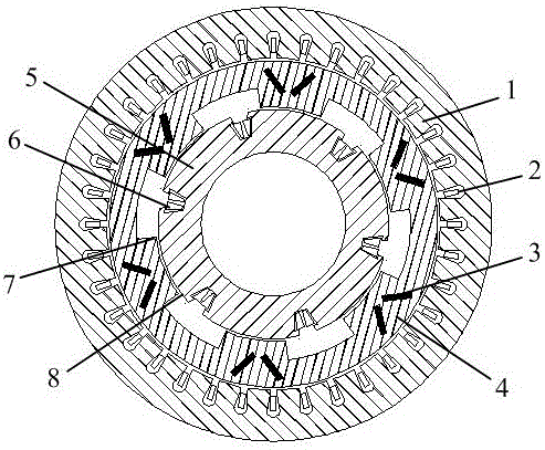
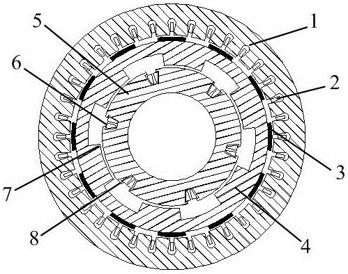
[0015] Such as figure 1 with figure 2 As shown, the present invention includes a stator 1, an outer rotor 4 and an inner rotor 5 assembled from the outside to the inside, the inner rotor 5 has inner rotor salient poles 8, and the three-phase centralized inner rotor winding 6 is embedded in the inner rotor slot; the outer rotor 4 There are permanent magnets 3 on the top, the radially inner surface of the outer rotor 4 has outer rotor salient poles 7, the radially outer surface of the outer rotor 4 is a cylindrical surface; the inner surface of the stator 1 is a cylindrical surface, and the three-phase distributed stator winding 2 Embedded in the stator slot.

[0016] The inner rotor 5 and the radial inner surface of the outer rotor 4 of the present invention constitute a salient pole type inner motor; the radial outer surface of the outer rotor 4 and the st...


PUM


Abstract

The invention discloses a permanent magnet-magnetic resistance radial magnetic-flux compound double-rotor motor. The motor comprises a stator (1), an external rotor (4) and an internal rotor (5) which are assembled from outside to inside. The internal rotor (5) possesses an internal-rotor salient pole (8). A three-phase centralized internal rotor winding (6) is embedded into an internal rotor groove. The external rotor (4) is provided with a permanent magnet (3). A radial internal surface of the external rotor (4) possesses an external-rotor salient pole (7). A radial external surface of the external rotor (4) is a cylindrical surface. An interior surface of the stator (1) is the cylindrical surface and a three-phase distributed stator winding (2) is embedded into a stator groove. In the invention, tooth space vibration and noises are effectively reduced, a power density and a power factor are improved and an output torque is increased.

Description

technical field [0001] The invention belongs to the field of hybrid electric vehicles, and in particular relates to a permanent magnet-reluctance radial flux composite double-rotor motor used for a hybrid electric vehicle. Background technique [0002] The motor used in hybrid electric vehicles is a doubly salient pole dual rotor motor, which includes two inner and outer rotors and a stator. Chinese patent document CN 103595159 A disclosed a double-salient-pole double-squirrel-cage outer rotor structure of a double-rotor motor on February 19, 2014. The feature of the outer rotor is that both the inner ring and the outer ring have salient poles, which is called a double-salient pole. Salient pole outer rotor, the outer rotor body is made of laminated silicon steel laminations, and two inner and outer squirrel cages are embedded on the outer rotor body, which can reduce rotor loss and enhance the rigidity of the cylindrical lamination outer rotor structure and strength. [0...

Claims


Application Information

Patent Timeline
Patent Type & Authority Applications(China)
IPC IPC(8): H02K16/02H02K1/27H02K1/24H02K1/16H02K3/28
CPCH02K16/02H02K1/165H02K1/24H02K1/2786H02K3/28
Inventor 徐奇伟孙静蒋小彪赵蒙罗骁枭李蕾玉
Owner CHONGQING UNIV
Why Eureka
Try Eureka