

Four-frequency laser gyro left and right circularly polarized light gyro signal separation device
A four-frequency laser gyro, circularly polarized light technology, applied in the laser field, can solve the problems of signal separation error, low gyro accuracy, poor signal separation accuracy, etc., to achieve accurate separation, improve gyro accuracy, and reduce signal separation errors.
Inactive Publication Date: 2011-06-08
FLIGHT AUTOMATIC CONTROL RES INST
View PDF0 Cites 1 Cited by
- Summary
- Abstract
- Description
- Claims
- Application Information
AI Technical Summary
Problems solved by technology
1. The accuracy of signal separation is poor
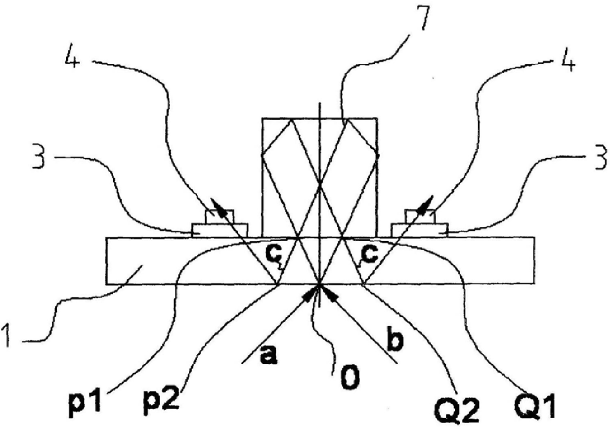
The mixed beam reflected and output from P2 and Q2 directly enters the separation component for separation, and the mixed beam is actually elliptically polarized light due to the error signal contained in it. After direct separation, the left-handed circularly polarized light gyro signal still has right-handed circular polarization. The optical gyro signal and the left-handed circularly polarized light gyro signal still remain in the right-handed circularly polarized light gyro signal, resulting in a large signal separation error and low gyro accuracy
Method used
View moreImage
Smart ImageViewing Examples

Examples
Embodiment Construction
Login to View More PUM
 Abstract
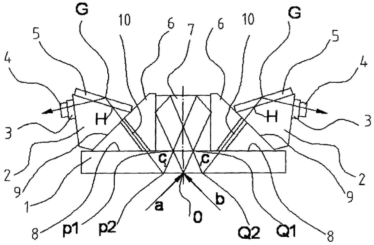
The invention belongs to the laser technology and relates to the improvement of a four-frequency laser gyro left and right circularly polarized light gyro signal separation device. It includes an output reflector [1], a combined light prism [7], two 1 / 4 wave plates [3] and two analyzers [4], and is characterized in that each 1 / 4 wave plate [3 ] and the output reflector [1] are installed with splitting prism [6], compensating prism [2] and reflector [5]. The invention can accurately realize signal separation, greatly reduces the signal separation error, and effectively improves the precision of the gyroscope. The output polarized light signal is in the form of positive emission, which increases the receiving strength of the signal and improves the signal-to-noise ratio.
Description
Four-frequency laser gyro left and right circularly polarized light gyro signal separation device technical field The invention belongs to the laser technology and relates to the improvement of a four-frequency laser gyro left and right circularly polarized light gyro signal separation device. Background technique There are both left-handed circularly polarized light and right-handed circularly polarized light in the resonant cavity of the four-frequency differential laser gyro. Both left-handed and right-handed circularly polarized light have two beams of light running clockwise and counterclockwise, forming a left-handed circularly polarized light gyro and a right-handed circularly polarized light. Circularly polarized light gyroscope. The difference between the two gyroscope signals can be used to obtain the measured rotation angle or angular velocity of the carrier space. Therefore, it is necessary to accurately separate the left-handed circularly polarized light gyro...
Claims
Login to View More Application Information
Patent Timeline
 Patent Type & AuthorityPatents(China)
IPC IPC(8): G02B27/10G02B27/28
Inventor韩宗虎刘元正陈林峰
OwnerFLIGHT AUTOMATIC CONTROL RES INST