Metal 3d printer

一种三维打印机、金属的技术,应用在金属加工设备、制造工具、加工环境调节等方向,能够解决制品品质下降、金属微粒子掉落、混入等问题,达到金属粒子减少、品质与安全性提高、生产效率提高的效果

Active Publication Date: 2017-01-25
SODICK CO LTD
View PDF11 Cites 26 Cited by
  • Summary
  • Abstract
  • Description
  • Claims
  • Application Information

AI Technical Summary

Problems solved by technology

Moreover, the metal particles in the smoke may also fall and be mixed into the new powder, resulting in a decline in the quality of the product.

Method used


Image

  • Metal 3d printer
  • Metal 3d printer
  • Metal 3d printer

Examples


Embodiment Construction

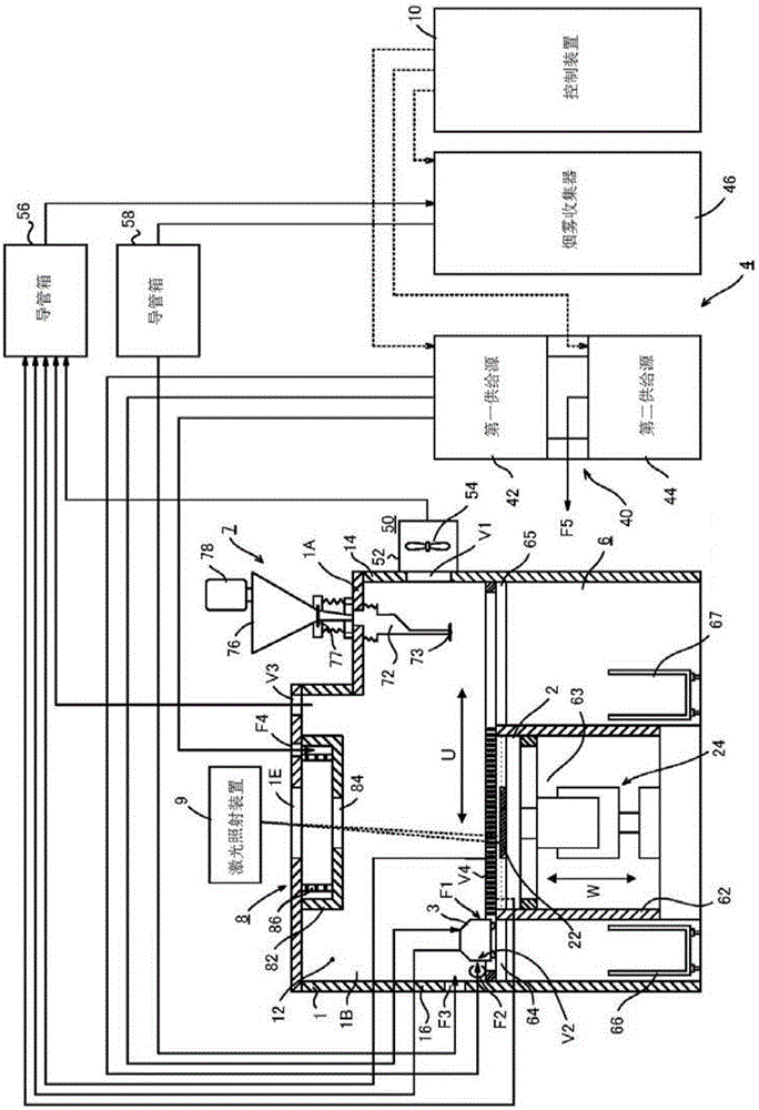
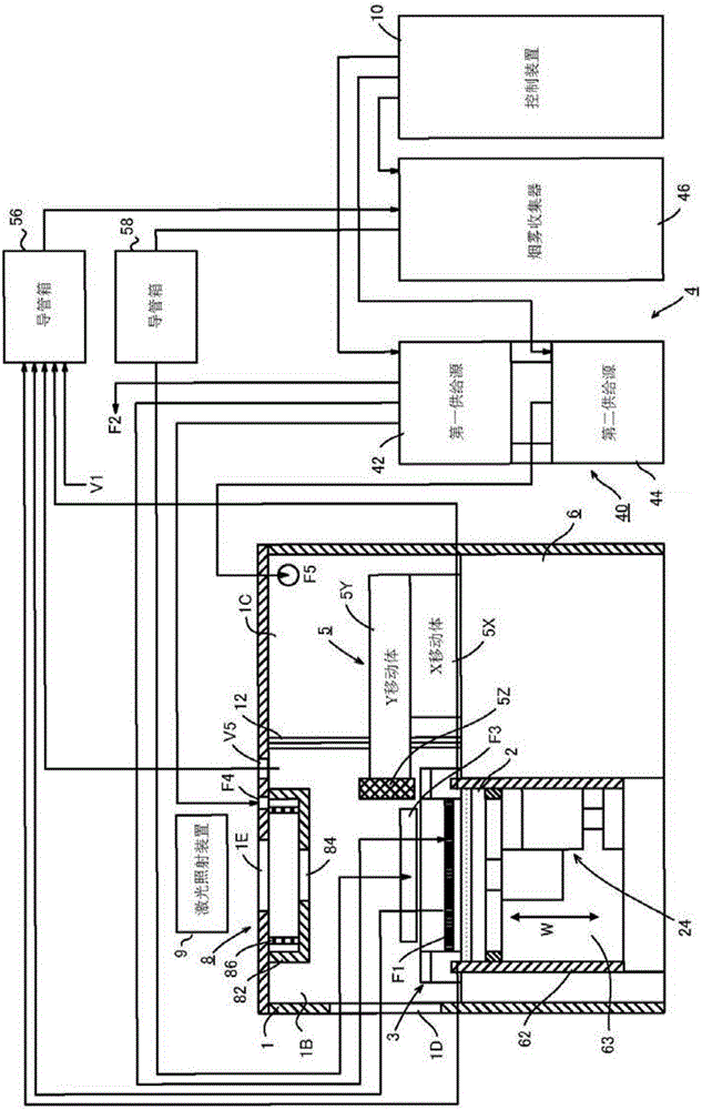
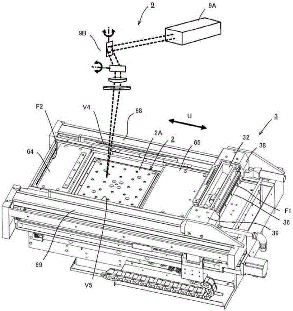
[0095] One embodiment of the present invention will be described in detail with reference to the drawings. figure 1 and figure 2 The dotted line in represents the signal line, image 3 The dotted line in indicates the irradiation path of the laser beam.

[0096] A metal 3D printer that repeatedly sinters metal powder to create a three-dimensional object is illustrated in figure 1 and figure 2 middle. The metal three-dimensional printer includes a housing 1 , a recoater head 3 , a material supply device 7 , an inert gas supply device 4 , a power supply device, a control device 10 and a fume collector 46 . The power supply unit, the control unit 10 and the smoke collector 46 are located at the rear of the casing 1 .

[0097] The casing 1 is a part that forms an environment in which the oxygen concentration is lower than a predetermined value. The casing 1 includes a top plate and four side walls, forming a closed chamber. The airtight chamber is partitioned by bellows 1...


PUM


Abstract

A metal 3D printer includes: a housing (1) forming a molding chamber (1B); a recoater head (3) reciprocating in the direction of a horizontal U axis in the molding chamber to form a powder layer of a metal; a laser irradiation device (9) irradiating an irradiation region in the powder layer with a laser beam to form a sintered layer; and an inert gas supply device (4). The inert gas supply device includes: a first suction port (V1) disposed on one (14) of the side walls facing each other in the direction of the U axis, which is far away from the irradiation region; a first blowout port (F1) disposed on a side of the recoater head to face the first suction port; and a second blowout port (F2) disposed to face the first suction port across the irradiation region.

Description

technical field [0001] The present invention relates to a metal 3D printer (metal 3D printer), which repeatedly sinters metal powder in a build chamber to laminate and manufacture a three-dimensional object as a product. In particular, the present invention relates to a metal three-dimensional printer provided with a device for removing fumes generated by sintering of metal powder from a manufacturing chamber. Background technique [0002] Known metal three-dimensional printers evenly spread metal powder on a table to form a thin powder layer, and irradiate a laser beam (laser beam) to a specific irradiation area in the powder layer to form a sintered layer. The desired three-dimensional object is produced by stacking multiple sintered layers. The metal 3D printer determines the irradiation area of ​​the laser beam for each division layer formed by dividing a three-dimensional object at a predetermined height. In other words, the metal 3D printer determines the irradiation...

Claims


Application Information

Patent Timeline
Patent Type & Authority Applications(China)
IPC IPC(8): B22F3/105B33Y30/00
CPCB33Y30/00B22F2999/00B22F10/00B22F10/77B22F12/38B22F10/28B22F12/52B22F10/322B22F12/70B22F12/67B33Y40/00B22F2201/10B22F2203/00B33Y50/02B29C64/214B29C64/371B29C64/25Y02P10/25
Inventor 川田秀一冈崎秀二
Owner SODICK CO LTD
Why Eureka
Try Eureka