Equipment and method for taking out chain pin shaft

A chain and pin technology, applied in the field of chain maintenance, can solve the problems of reduced strength of pins and chain plates, failure to meet working strength requirements, changes in mechanical properties of chains, etc., to achieve rapid removal, increase labor productivity, and save costs. Effect

Inactive Publication Date: 2017-01-25
PANGANG GRP XICHANG STEEL & VANADIUM CO LTD
View PDF6 Cites 3 Cited by
  • Summary
  • Abstract
  • Description
  • Claims
  • Application Information

AI Technical Summary

Problems solved by technology

[0006] 1. When using hand hammers and copper rods to take out, the knocking time is long, the work efficiency is low, and continuous operation is prone to fatigue, and hand hammers are easy to hit hands and hurt people, which can easily cause safety accidents;
[0007] 2. When heating is used to take it out, the strength of the pin shaft and chain plate will be reduced, resulting in changes in the mechanical properties of the chain, which cannot meet the corresponding working strength requirements

Method used


Image

  • Equipment and method for taking out chain pin shaft
  • Equipment and method for taking out chain pin shaft
  • Equipment and method for taking out chain pin shaft

Examples


Embodiment 1

[0046] The overall size of the equipment for taking out the chain pin shaft is a vertical equipment with a length of 750mm, a width of 470mm, and a height of 1300mm.

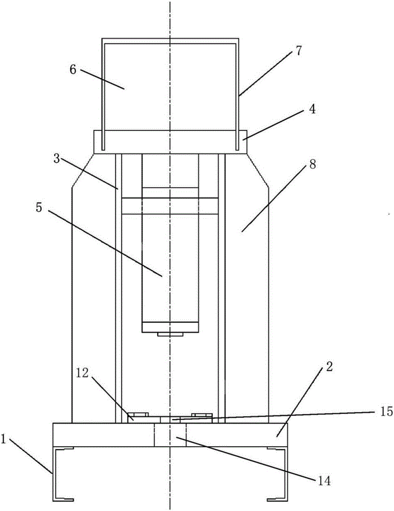
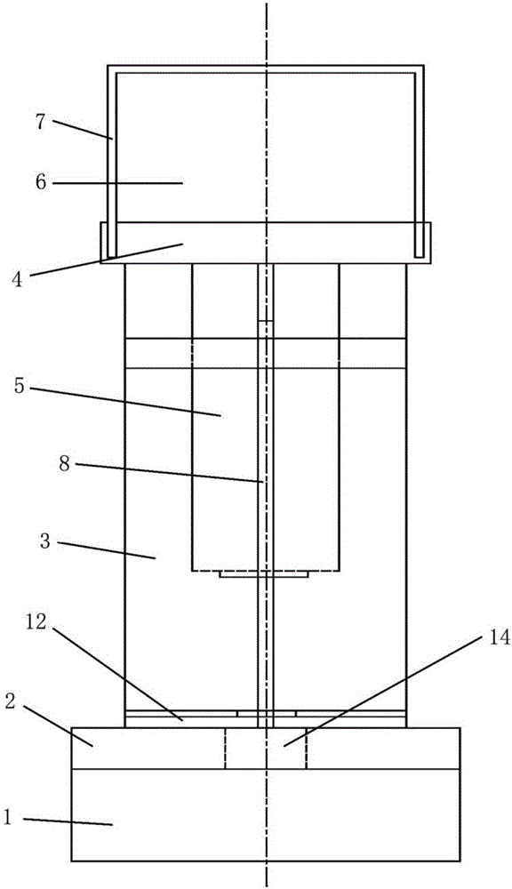
[0047] Use a steel plate with a thickness of 70mm and the material is Q235 according to the design figure 1 and figure 2 Make the upper base plate 4 of the base frame and the lower base plate 2 of the base frame, use Q235 steel plate with a thickness of 20mm as the supporting connecting plate 3 on both sides, and vertically support the connecting plate 3, the upper base plate 4 of the base frame and the lower base plate 2 of the base frame Weld the reinforcing plate 8 to increase the strength. 200mm carbon channel steel is used as the base 1, and a gap of about 170mm is formed with the ground to facilitate cleaning of the pin shaft.

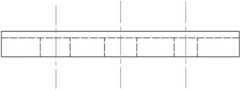
[0048] The bottom plate 4 of the base frame is a steel plate of 500mm*400mm*70mm, with 4 ring-shaped openings in the center. Round hole, used to fix the bottom of the hydrauli...

Embodiment 2

[0053] (1) Clean the oil on the chain to be repaired, and remove the upper check pin.

[0054] (2) Check that there is no oil leakage in the hydraulic system of the device, the system working pressure gauge, and the design limit pressure gauge (30Mpa) ensure that the system is normal.

[0055] (3) According to the size of the chain, select the appropriate movable bottom plate mold and the corresponding aperture and install it.

[0056] (4) Put the chain on the movable bottom plate, and the pin shaft is facing the pin shaft hole of the movable bottom plate.

[0057] (5) Use the guide rod (diameter smaller than the chain pin shaft 20 ~ 25mm) to resist, start the hydraulic system, the hydraulic cylinder pressure head is slowly pressed down, so that the guide rod bears the pre-tightening force, then suspend the pressure of the hydraulic system, and fine-tune the guide rod And chain, the pin shaft of chain is perpendicular to base plate, and the center of circle of guide bar is ju...


PUM


Abstract

The present invention provides an apparatus and method for removing a chain pin. The equipment for taking out the chain pin includes a hydraulic system, a base frame support device, and a movable base plate (12), wherein the base frame support device includes a base (1), a base frame lower base plate (2), a support connecting plate (3), The upper base plate (4) of the base frame, the hydraulic system includes a hydraulic cylinder (5), a hydraulic power system (6), a pressure detection device, a pressure protection device and a pipeline, and the movable base plate (12) is provided with a pin corresponding to the chain pin shaft hole (14). When in use, select a movable bottom plate with a suitable aperture according to the size of the chain, place the chain on the movable bottom plate, and use the hydraulic system to press out the chain pin. The invention can quickly dismantle the switch chain pins, improve the efficiency of chain dismantling and maintenance, eliminate the potential safety hazards of manually knocking and dismantling the pins, effectively remove the chain and other chain pins, and have a wide range of applications.

Description

technical field [0001] The invention relates to the technical field of chain maintenance, in particular to a device and method for taking out a chain pin. Background technique [0002] At present, the coke oven hydraulic switch used by Pangang Xichang Steel Vanadium Panjiang Coal Chemical Plant is one of the key auxiliary equipment of the coke oven. There are four coke ovens in Panjiang Coal Chemical Plant of Xichang Iron and Steel Vanadium in Panzhihua Iron and Steel Co., Ltd. Each coke oven has 56 carbonization chambers, and each carbonization chamber corresponds to a gas replacement device. The gas replacement device is connected with the hydraulic exchange line, and the valve of the gas replacement device is kept open and closed through the reciprocating operation of the hydraulic cylinder. Chain connection is used at the corners on both sides of the coke oven to achieve the purpose of pull steering. [0003] However, the overall span of the hydraulic switchboard is la...

Claims


Application Information

Patent Timeline
Patent Type & Authority Applications(China)
IPC IPC(8): B23P19/027
CPCB23P19/027
Inventor 杜刚邓东李春辉陈建
Owner PANGANG GRP XICHANG STEEL & VANADIUM CO LTD
Why Eureka
Try Eureka