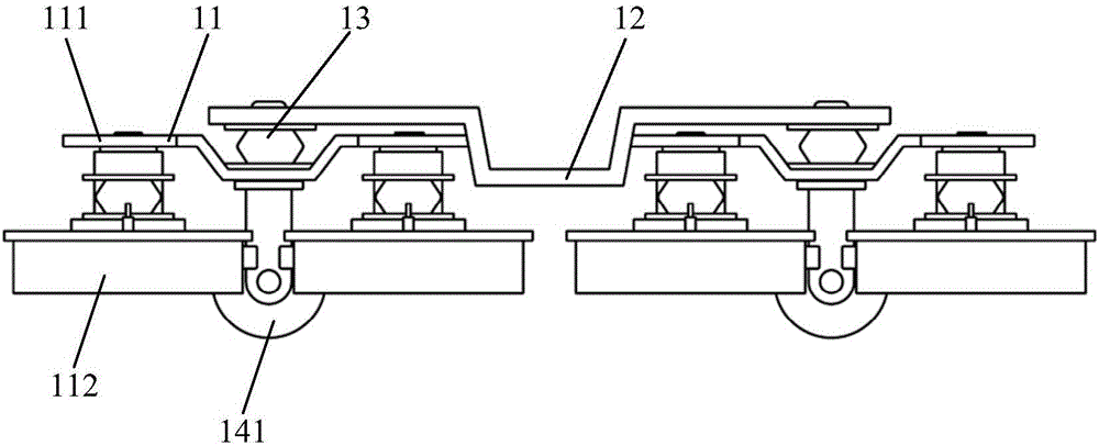
Superconducting maglev vehicle bogie
A technology for maglev vehicles and bogies, which is applied to devices that move laterally between the chassis and the bogies, electric vehicles, and vehicle components, etc. Problems, to achieve the effect of improving load capacity, strong suspension guiding effect, and increasing load capacity
- Summary
- Abstract
- Description
- Claims
- Application Information
AI Technical Summary
Problems solved by technology
Method used
Image
Examples
specific Embodiment 1
[0067] Embodiment 1: The extending direction of the connecting beam is the same as that of the vehicle body, and the extending direction of the N-level beam is the same as that of the connecting beam.
[0068] For example, figure 1 It is a side view of the superconducting maglev vehicle bogie in Embodiment 1 of the present invention, figure 2 It is a simple schematic diagram of the top view of the superconducting maglev vehicle bogie in the first embodiment of the present invention. Such as figure 1 and figure 2 As shown, preferably, in the specific embodiment one of the present invention, the bogie of the superconducting maglev vehicle mainly includes: a secondary beam 12 and two suspension guide units 11; the two ends of the secondary beam 12 The middle parts of the connecting beams 111 of two adjacent suspension guiding units 11 are respectively connected with the rotating shaft 110 ; each suspension guiding unit includes: a connecting beam 111 and two Dewars 112 . Th...
specific Embodiment 2
[0080] Embodiment 2: The extending direction of the connecting beam is perpendicular to the extending direction of the vehicle body, and the extending direction of the N-level beam is perpendicular to the extending direction of the connecting beam.
[0081] For example, Figure 7 It is a side view of the superconducting maglev vehicle bogie in the second embodiment of the present invention, Figure 8 It is a simple schematic diagram of the top view of the superconducting maglev vehicle bogie in the second embodiment of the present invention. Such as Figure 7 and Figure 8 As shown, preferably, in the specific embodiment 2 of the present invention, the bogie of the superconducting maglev vehicle mainly includes: a secondary beam 22 and two suspension guide units 21; the two ends of the secondary beam 22 The middle parts of the connecting beams 211 of two adjacent suspension guiding units 21 are respectively connected with the rotating shaft 210 ; each suspension guiding uni...
specific Embodiment 3
[0092] Specific embodiment three: the extending direction of the connecting beam is the same as that of the vehicle body, and the extending direction of the N-level beam is the same as or perpendicular to the extending direction of the connecting beam.
[0093] For example, Figure 13 It is a simple schematic diagram of the top view of the superconducting maglev vehicle bogie in the third embodiment of the present invention. Such as Figure 13 As shown, preferably, in the third specific embodiment of the present invention, the bogie of the superconducting maglev vehicle mainly includes: a secondary beam 32 and two suspension guide units 31; the two ends of the secondary beam 32 The middle parts of the connecting beams 311 of two adjacent suspension guiding units 31 are respectively connected with the rotating shaft 310 ; each suspension guiding unit includes: a connecting beam 311 and two Dewars 312 . Therefore, at this time, N=2, and the superconducting maglev vehicle bogie...
PUM
 Abstract
Description
Claims
Application Information
 - R&D
- Intellectual Property
- Life Sciences
- Materials
- Tech Scout
- Unparalleled Data Quality
- Higher Quality Content
- 60% Fewer Hallucinations
Browse by: Latest US Patents, China's latest patents, Technical Efficacy Thesaurus, Application Domain, Technology Topic, Popular Technical Reports.
© 2025 PatSnap. All rights reserved.Legal|Privacy policy|Modern Slavery Act Transparency Statement|Sitemap|About US| Contact US: help@patsnap.com


