Explosive-proof cabin crane capable of centrally and fixedly arranging driving device at end part

A driving device, translational driving device technology, applied in safety devices, lifting equipment in mines, walking mechanisms, etc., can solve the problems of high price, large size, limited height of ship engine room, etc., achieve large lifting net height, increase The effect of cabin storage capacity

Inactive Publication Date: 2017-01-25
中国船舶重工集团公司第七0四研究所
View PDF5 Cites 5 Cited by
  • Summary
  • Abstract
  • Description
  • Claims
  • Application Information

AI Technical Summary

Problems solved by technology

When there is explosive gas or dust in the engine room, it is difficult to carry out cable protection, and it is difficult to ensure the integrity of the explosion-proof characteristics of the system, and it is contrary to GB / T17436-1998 ("Selection of Explosion-proof Electrical Equipment in Hazardous Areas of Ships"), Section 5.3 "by cables Powered portable devices should not be used in hazardous areas"
[0003] Moreover, in order to improve the safety of the system, the existing explosion-proof cabin driving must adopt the intrinsically safe electronic control system, which is expensive
In addition, the upper and lower structures (including the motor) of the driving bridge in the workshop are large in size, while the height of the ship's engine room is limited

Method used


Image

  • Explosive-proof cabin crane capable of centrally and fixedly arranging driving device at end part
  • Explosive-proof cabin crane capable of centrally and fixedly arranging driving device at end part
  • Explosive-proof cabin crane capable of centrally and fixedly arranging driving device at end part

Examples


Embodiment Construction

[0021] The present invention will be further described below with reference to the drawings and embodiments.

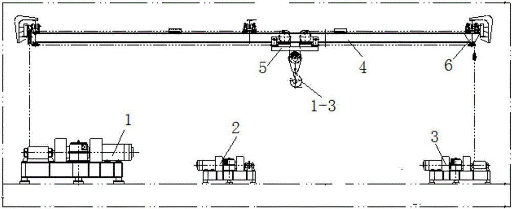
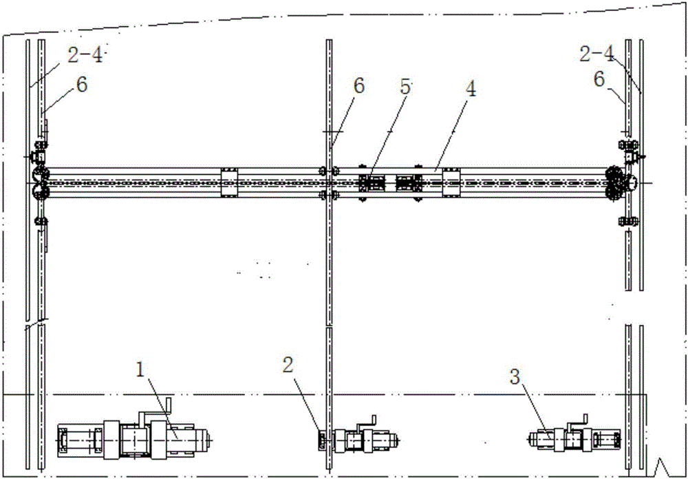
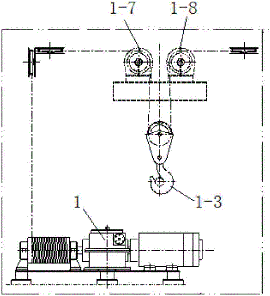
[0022] Such as figure 1 , As shown in 2, the driving device of the present invention is centralized and fixedly arranged at the end of the explosion-proof nacelle crane, which is mainly composed of the lifting and lowering driving device 1, the longitudinal translation driving device 2, the transverse translation driving device 3, the double beam bridge 4, and the translation trolley 5. , Orbit 6 and other components.

[0023] Three rails 6 are installed under the roof of the nacelle and arranged longitudinally. Two rails 6 are on both sides of the nacelle, and one rail 6 is in the middle of the cabin. The double-beam bridge 4 is movably connected to the three rails 6 through a pulley block. The double-beam bridge 4 is equipped with a translation trolley 5, the upper and lower sides of the nacelle are respectively equipped with a lifting and lowering drive device 1, a hori...


PUM


Abstract

The invention relates to an explosive-proof cabin crane capable of centrally and fixedly arranging a driving device at an end part. The explosive-proof cabin crane is characterized in that three rails are arranged under a cabin ceiling in a longitudinal direction; a double girder bridge is movably connected with the three rails through pulley blocks; a translation trolley is arranged in the middle part of the double girder bridge; a hoisting and lifting driving device and a transverse translation driving device are respectively arranged at both sides of the upper surface of the bottom part of a cabin, a longitudinal translation driving device is arranged in the middle part of the cabin, the hoisting and lifting driving device is connected with a hook assembly on the translation trolley through a steel wire rope and the pulley blocks, and the longitudinal translation driving device is connected with the double girder bridge through a transmission chain, an upper chain wheel assembly and a dragging chain; the transverse translation driving device is connected with two pulleys on the translation trolley through two steel wire ropes and the pulley blocks. The explosive-proof cabin crane has the advantages that by adopting a steel wire rope penetrating and winding manner, the breakthrough of a transmission technique is realized, a following cable of the explosive-proof cabin is not needed, the problem of difficulty in explosion prevention of the cabin crane in dangerous occasions is solved, the installation and maintenance cost of a system is reduced, and the lifting clearance height is increased.

Description

Technical field [0001] The invention relates to a ship engine room crane, in particular to an explosion-proof engine room crane with a driving device centrally fixedly arranged at the end of the ship. Background technique [0002] Like general workshop cranes, the existing marine engine room cranes use three motors to drive the lifting device, longitudinal translation device, and lateral translation device respectively. The motors are installed on the bridge or upside down under the bridge. The motor needs power Cables and control cables required for control move along with the bridge frame and the trolley. When there is explosive gas or dust in the engine room, it is difficult to carry out cable protection, and it is difficult to ensure the integrity of the system's explosion-proof characteristics, and it is contrary to GB / T17436-1998 ("Selection of explosion-proof electrical equipment in hazardous areas of ships"), section 5.3 related to "Cable Powered portable equipment shoul...

Claims


Application Information

Patent Timeline
IPC IPC(8): B66B17/06B66C9/14B66C11/02B66C15/00
CPCB66B17/06B66C9/14B66C11/02B66C15/00
Inventor 樊仁才吕堂祺张晓东胡职焱扬子江
Owner 中国船舶重工集团公司第七0四研究所
Why Eureka
Try Eureka