Simply supported girder bridge floor continuous new construction and construction method

A technology of simply supported beam bridges and structures, applied in bridges, bridge parts, bridge construction, etc., can solve problems such as low void ratio, and achieve the effect of improving anti-corrosion performance

Inactive Publication Date: 2015-05-13
FUZHOU UNIV
View PDF5 Cites 13 Cited by
  • Summary
  • Abstract
  • Description
  • Claims
  • Application Information

AI Technical Summary

Problems solved by technology

[0004] In order to solve the existing technical deficiencies, the present invention provides a new continuous structure and construction method of simply supported beam bridge deck, by using the tensile properties and toughness of the ultra-high performance concrete connecting plate to realize the temperature drop load, the concrete shr...

Method used


Image

  • Simply supported girder bridge floor continuous new construction and construction method
  • Simply supported girder bridge floor continuous new construction and construction method
  • Simply supported girder bridge floor continuous new construction and construction method

Examples


Embodiment Construction

[0036] In order to make the above-mentioned features and advantages of the present invention more comprehensible, the following specific embodiments are described in detail with reference to the accompanying drawings.

[0037] The specific implementation of the structure involved in the present invention is as follows:

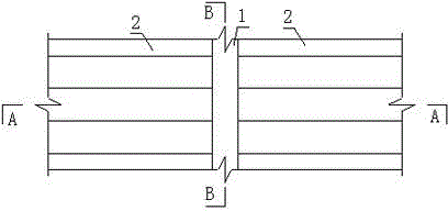
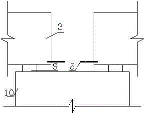
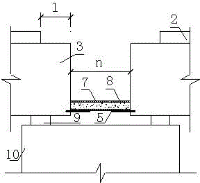
[0038] The ultra-high performance concrete connecting plate 1 is arranged between the bridge decks 2 of adjacent main girders of a simply supported girder bridge, and is combined with the bridge decks 2 of adjacent main girders to form a continuous whole structure of the bridge deck. The length m of the ultra-high performance concrete connecting plate is equal to the distance between the bridge decks of adjacent girders. The distance between the end faces of adjacent girders is n. A non-adhesive layer 4 is set between the ultra-high performance concrete connecting plate 1 and the main beam 3 . The length of the non-adhesive layer is l. The steel arc-shaped ...


PUM


Abstract

The invention relates to simply supported girder bridge floor continuous new construction. The construction comprises multiple girders of a simply supported girder bridge and bridge floor plates arranged on the girders, ultra-high performance concrete connecting plates are arranged and connected between the bridge floor plates on the adjacent girders, arc-shaped steel supporting pieces located at the same height are embedded in end faces of the adjacent girders, steel tube ultra-high performance concrete segments are arranged between the arc-shaped steel supporting pieces, two ends of each steel tube ultra-high performance concrete segment are connected with end faces of the girder at corresponding side respectively, and the invention further relates to two construction methods applied to new-built simply supported girder bridge and existing simply supported girder bridge. By utilizing the ultra-high performance concrete connecting plates arranged in the simply supported girder bridge floor continuous new construction, tensile deformation in longitudinal direction of a bridge at continuous construction on bridge floor caused by girder deformation of the adjacent girders is achieved, and corrosion resistant performance is improved; and by utilizing compression resistance performances of the ultra-high performance concrete connecting plates and the steel tube ultra-high performance concrete segments, compression deformation in longitudinal direction of the bridge at the continuous construction on the bridge floor caused by the girder deformation of the adjacent girders is achieved.

Description

technical field [0001] The invention relates to a new continuous structure and construction method of a simply supported beam bridge deck, which belongs to the field of bridges. Background technique [0002] The jumping caused by the bridge expansion joints and the secondary adverse effects caused by the damage of the expansion joints (such as the additional internal force of the structure, the corrosion of the structure by water leakage, etc.) are often encountered in the actual operation of bridges at home and abroad. Tricky question. The jumping caused by the telescopic device not only has a great impact on the bridge, but also reduces the driving comfort of the driver and passengers. In addition, as the traffic flow increases day by day, the maintenance and replacement of the expansion joint device will often cause serious traffic interruptions, resulting in huge economic losses. It can be seen that it is imperative to solve a series of problems caused by bridge expans...

Claims


Application Information

Patent Timeline
IPC IPC(8): E01D19/12E01D21/00
CPCE01D19/125E01D21/00
Inventor 陈宝春薛俊青
Owner FUZHOU UNIV
Why Eureka
Try Eureka