Friction abrasion testing machine

A friction and wear test and test device technology, applied in the direction of testing wear resistance, etc., can solve the problems of complex friction and wear research, waste of robot force, material resources and financial resources, etc., to shorten the test period, reduce the test cost, and enrich the test forms. Effect

Active Publication Date: 2017-01-25
SOUTH CHINA UNIV OF TECH
View PDF11 Cites 7 Cited by
  • Summary
  • Abstract
  • Description
  • Claims
  • Application Information

AI Technical Summary

Problems solved by technology

[0002]Modern industry is developing faster and faster, but there are also many problems. Among them, the wear and tear of machines has caused a great waste of manpower, material and financial resources. The research on the friction and wear performance plays a pivotal role, including the bench research on the friction and wear of the whole machine and parts, and the research on the friction and wear mechanism of the corresponding materials. However, the research on friction and wear is very complicated, different working conditions and different motion forms And different contact pairs will produce different changes, so a multifunctional friction and wear testing machine is very necessary

Method used


Image

  • Friction abrasion testing machine
  • Friction abrasion testing machine
  • Friction abrasion testing machine

Examples


Embodiment 1

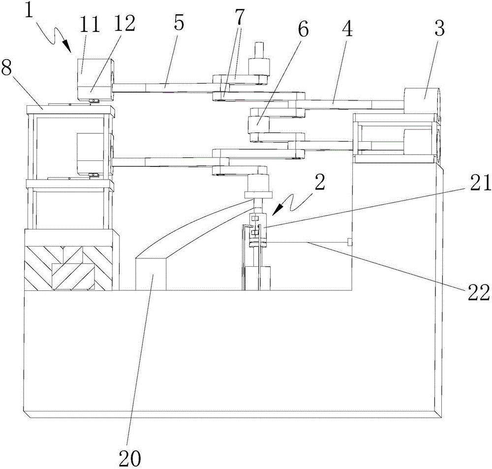
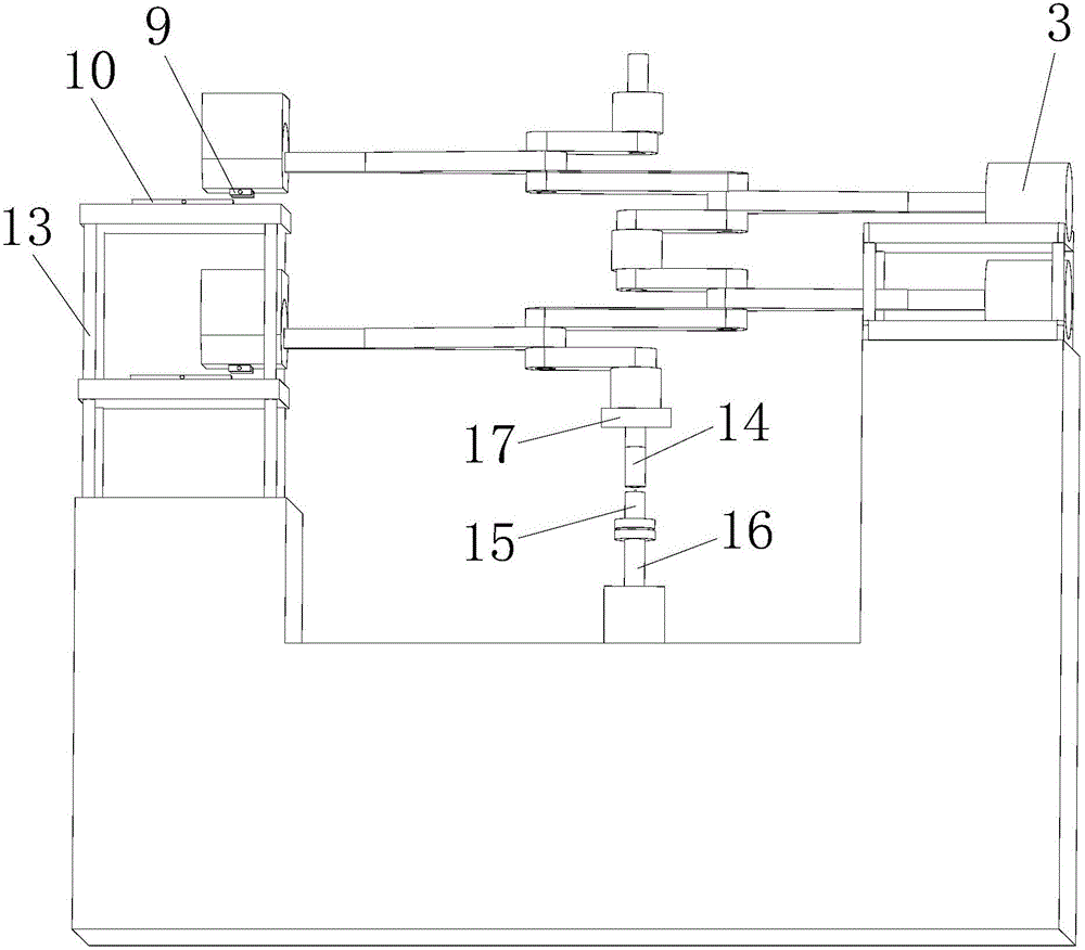
[0023] A friction and wear testing machine, comprising a sliding friction test device 1, a rotary friction test device 2 and a power mechanism that provides power to the sliding friction test device and the rotary friction test device, the power mechanism includes a cylinder 3, a crankshaft, a drive connecting rod 4 and a diameter To the output connecting rod 5, the crankshaft has a connecting rod 7 and an axially staggered main journal 6, a first connecting rod journal axis, and a second connecting rod journal axis. The main journal is located on the main axis of the crankshaft, and the first connecting rod journal axis and The second connecting rod journal is located on both sides of the main axis of the crankshaft. The main journal, the first connecting rod journal and the second connecting rod journal are respectively connected by connecting rods. One end of the driving connecting rod is hinged to the cylinder, and the other end is connected to the second connecting rod. On...


PUM


Abstract

The invention discloses a friction abrasion testing machine. The friction abrasion testing machine comprises a sliding friction testing device, a rotary friction testing device and a power mechanism for supplying power to the sliding friction testing device and the rotary friction testing device; the power mechanism comprises an air cylinder, a bent axle, a driving connecting rod and a radial output connecting rod; the bent axle is provided with a connecting rod, and a main shaft neck, a first connecting rod neck shaft and a second connecting rod neck shaft which are arranged in an axial staggered manner; the main shaft neck, the first connecting rod neck shaft and the second connecting rod neck shaft are connected together through the connecting rod respectively; one end of the driving connecting rod is hinged to the air cylinder and the other end of the driving connecting rod is connected with the first connecting rod neck shaft; one end of the radial output connecting rod is connected with the second connecting rod neck shaft and the other end of the radial output connecting rod is connected with the sliding friction testing device; the main shaft neck at the end part of the bent axle is connected with the rotary friction testing device. The friction abrasion testing machine can be used for carrying out a linear reciprocated friction test and a rotary friction test, the problem that friction tests with different movement forms need different testing devices is solved and the testing cost is reduced.

Description

technical field [0001] The invention relates to a testing device, in particular to a friction and wear testing machine. Background technique [0002] The development of modern industry is getting faster and faster, but there are also many problems. Among them, the wear of machines has caused a great waste of manpower, material resources and financial resources. Bench research on the friction and wear of parts, as well as the research on the friction and wear mechanism of corresponding materials, and the research on friction and wear is very complicated, different working conditions, different motion forms and different contact pairs will produce different changes, so the multifunctional friction Wear testing machine is very necessary. Contents of the invention [0003] Aiming at the technical problems existing in the prior art, the purpose of the present invention is to provide a friction and wear testing machine. [0004] The purpose of the present invention is achieved...

Claims


Application Information

Patent Timeline
Patent Type & Authority Applications(China)
IPC IPC(8): G01N3/56
CPCG01N3/56
Inventor 屈盛官尹联民赖福强肖传伟李小强
Owner SOUTH CHINA UNIV OF TECH
Why Eureka
Try Eureka