MOEMS (micro optical electronic mechanical system) laser scanning micromirror array speckle suppression device

A scanning micromirror and suppression device technology, applied in optics, optical components, instruments, etc., can solve the problems of cumbersome operation process, large volume structure, complex structure, etc., and achieve the effect of convenient operation, small volume and simple structure

Inactive Publication Date: 2017-01-25
SHANXI UNIV
View PDF7 Cites 20 Cited by
  • Summary
  • Abstract
  • Description
  • Claims
  • Application Information

AI Technical Summary

Problems solved by technology

[0005] The purpose of the present invention is to overcome the shortcomings of the prior art, provide a MOEMS laser scanning micromirror array speckle suppression device, and solve th

Method used


Image

  • MOEMS (micro optical electronic mechanical system) laser scanning micromirror array speckle suppression device
  • MOEMS (micro optical electronic mechanical system) laser scanning micromirror array speckle suppression device

Examples


Embodiment 1

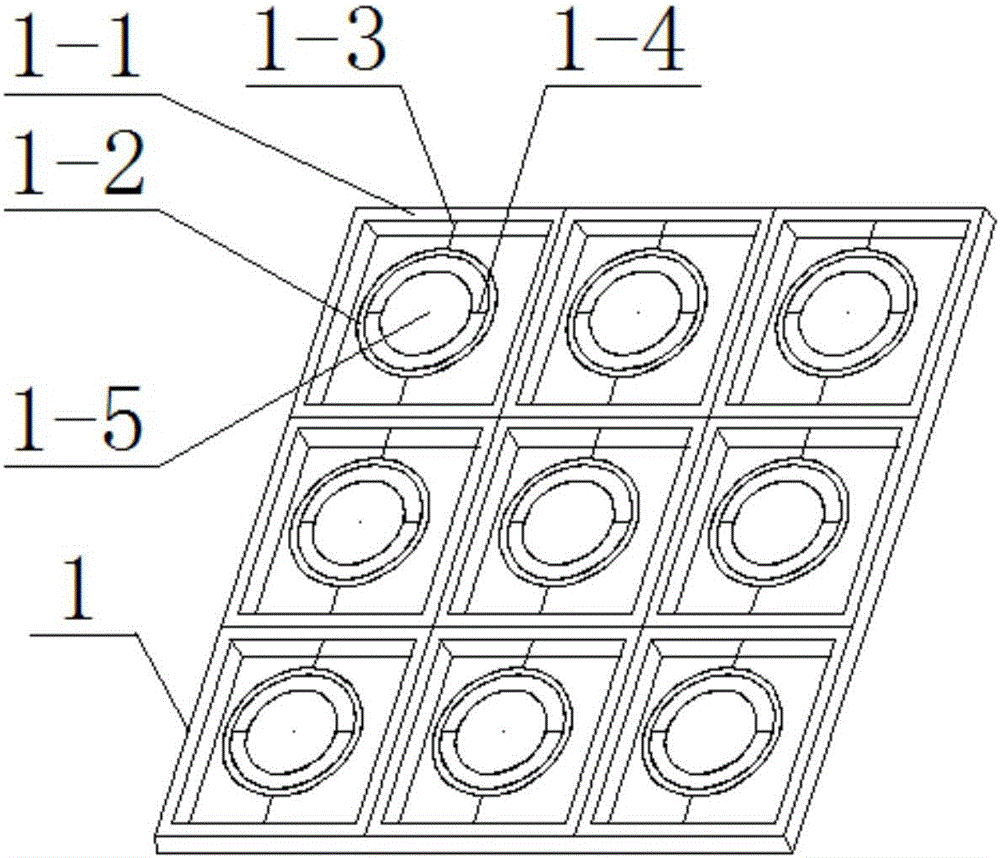
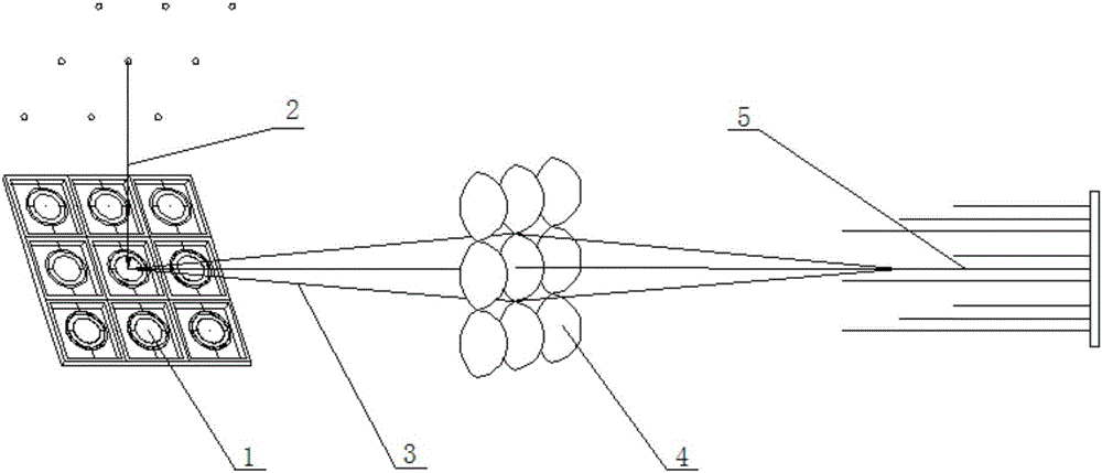
[0021] A MOEMS laser scanning micromirror array speckle suppression device is composed of 3×3 scanning micromirrors 1, and a single scanning micromirror consists of a fixed anchor point 1-1 rotating along the X axis and a fixed anchor point 1-1 rotating along the Y axis 2. The torsion beam 1-3 rotating along the X axis, the torsion beam 1-4 rotating along the Y axis and the mirror surface 1-5 are composed. The torsion beam 1-3 rotating along the X axis is connected to the Between the rotating fixed anchor point 1-1 and the fixed anchor point 1-2 rotating along the Y axis, the torsion beam 1-4 rotating along the Y axis is connected to the fixed anchor point 1-2 rotating along the Y axis Between the mirror surface 1-5; under the drive of electromagnetic force or electrostatic force, etc., synchronously control all scanning micromirrors to realize scanning in X and Y directions; or independently control a single scanning micromirror to realize scanning in X and Y directions ; The...

Embodiment 2

[0023] A MOEMS laser scanning micromirror array speckle suppression device is composed of 1×3 scanning micromirrors 1, and a single scanning micromirror consists of a fixed anchor point 1-1 rotating along the X axis and a fixed anchor point 1-1 rotating along the Y axis 2. The torsion beam 1-3 rotating along the X axis, the torsion beam 1-4 rotating along the Y axis and the mirror surface 1-5 are composed. The torsion beam 1-3 rotating along the X axis is connected to the Between the rotating fixed anchor point 1-1 and the fixed anchor point 1-2 rotating along the Y axis, the torsion beam 1-4 rotating along the Y axis is connected to the fixed anchor point 1-2 rotating along the Y axis Between the mirror surface 1-5; under the drive of electromagnetic force or electrostatic force, etc., synchronously control all scanning micromirrors to realize scanning in X and Y directions; or independently control a single scanning micromirror to realize scanning in X and Y directions ; The...

Embodiment 3

[0025] A MOEMS laser scanning micromirror array speckle suppression device is composed of 2×3 scanning micromirrors 1, and a single scanning micromirror consists of a fixed anchor point 1-1 rotating along the X axis and a fixed anchor point 1-1 rotating along the Y axis 2. The torsion beam 1-3 rotating along the X axis, the torsion beam 1-4 rotating along the Y axis and the mirror surface 1-5 are composed. The torsion beam 1-3 rotating along the X axis is connected to the Between the rotating fixed anchor point 1-1 and the fixed anchor point 1-2 rotating along the Y axis, the torsion beam 1-4 rotating along the Y axis is connected to the fixed anchor point 1-2 rotating along the Y axis Between the mirror surface 1-5; under the drive of electromagnetic force or electrostatic force, etc., synchronously control all scanning micromirrors to realize scanning in X and Y directions; or independently control a single scanning micromirror to realize scanning in X and Y directions ; The...


PUM


Abstract

An MOEMS laser scanning micromirror array speckle suppressing device relates to beam control optical fiber speckle elimination technology, which solves the technical problems of the existing laser speckle suppressing device with large volume and structure, high power consumption, complex structure and cumbersome operation process. The present invention is composed of M×N scanning micromirrors, and a single scanning micromirror consists of a fixed anchor point rotating along the X axis, a fixed anchor point rotating along the Y axis, a torsion beam rotating along the X axis, and a torsion beam rotating along the Y axis Composed of reflective mirrors; under the drive of electromagnetic force or electrostatic force, etc., synchronously control all scanning micromirrors to realize scanning in X and Y directions; or independently control a single scanning micromirror to realize scanning in X and Y directions; the reflection The mirror surface is a circular mirror surface, a square mirror surface, an arc mirror surface or other irregular shapes. The laser speckle suppression device of the present invention has the advantages of small size, low power consumption, simple structure, easy integration and convenient operation under the premise of achieving the same speckle suppression effect.

Description

technical field [0001] The invention belongs to the technical field of light beam regulation optical fiber speckle elimination, and in particular relates to a MOEMS laser scanning micromirror array speckle suppression device. Background technique [0002] Generally, existing technologies utilize the monochromatic and directional properties of lasers, which are widely used in laser lighting, such as laser displays. [0003] When a coherent laser beam is transmitted through a rough scatterer or is reflected by a rough scatterer, the interference of light waves will occur on the rough surface of the scatterer: speckle, which shows granular non-uniform light and dark light intensity distribution. In laser displays, the presence of speckle degrades image quality and must be suppressed. [0004] At present, limited by the optical power of laser diodes, fiber-optic coupling is generally used in high-lumen laser displays to integrate multiple collimated red, green, and blue laser ...

Claims


Application Information

Patent Timeline
IPC IPC(8): G02B27/48G02B26/10
CPCG02B27/48G02B26/105
Inventor 仝召民陈旭远贾锁堂
Owner SHANXI UNIV
Why Eureka
Try Eureka