
Charging station charging system for super-capacitor vehicle and control method

A charging system and charging station technology, applied in electric vehicles, battery circuit devices, current collectors, etc., can solve the problems of wasting passenger time, long parking and charging time, and prolonging operation time, and achieve the effect of avoiding arcing

Active Publication Date: 2017-01-25
XIANGTAN ELECTRIC MFG CORP LTD
View PDF8 Cites 8 Cited by
  • Summary
  • Abstract
  • Description
  • Claims
  • Application Information

AI Technical Summary

Problems solved by technology

This solution avoids the potential safety hazards caused by the long-term electrification of the power supply rail of the charging station and the arc phenomenon caused by the bow raising and lowering of the super electric vehicle. However, this solution requires the supercapacitor to be fully charged before disconnecting the power supply rail for power supply and lowering the bow. drive
In reality, since the number of people getting on and off at each station is not fixed, it will take too long to park and recharge every time it needs to be fully charged, which prolongs the operating time of each bus and wastes the time of passengers.

Method used


Image

  • Charging station charging system for super-capacitor vehicle and control method
  • Charging station charging system for super-capacitor vehicle and control method
  • Charging station charging system for super-capacitor vehicle and control method

Examples


Embodiment Construction

[0021] The present invention will be further described below in conjunction with the accompanying drawings and embodiments.

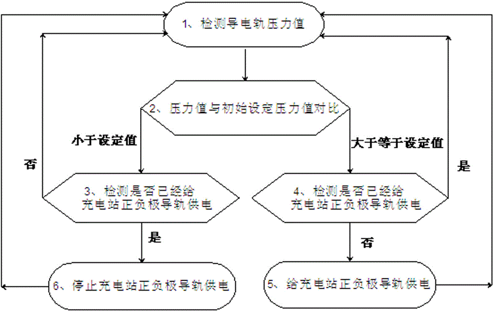
[0022] Refer to attached figure 1 , a supercapacitor vehicle charging station charging system, which includes: a controller 8, a rectifier module 1 connected to the grid, a high-frequency converter module 2 connected to the rectifier module 1, and a high-frequency converter module 2 connected The high-frequency transformer module 3, the DC circuit breaker 5 connected to the high-frequency transformer module 3, the positive and negative guide rails 6 of the charging station connected to the DC circuit breaker 5, and the positive and negative guide rails installed on the charging station respectively The two pressure sensors 7 on the top are respectively used to detect the contact pressure between the pantograph of the supercapacitor vehicle and the positive and negative guide rails of the charging station, and the controller 8 compares the pressure value...


PUM


Abstract

The invention relates to a charging station charging system for a super-capacitor vehicle. The system comprises a controller, a rectification module, a high-frequency converter module, a direct current circuit breaker, charging station anode and cathode guide rails as well as two pressure sensors mounted on the charging station anode and cathode guide rails respectively, wherein when the pressure values of the two pressure sensors are both larger than or equal to a set initial pressure value, the controller outputs a switching-on signal for the direct current circuit breaker, after the direct current circuit breaker is switched on, the controllers sends a high-frequency converter module starting signal, and charging of the super-capacitor vehicle is started. When the pressure value of one or two of the pressure sensors is smaller than the set value, charging of the super-capacitor vehicle is stopped. The charging station anode and cathode guide rails can be supplied with power only when the measured pressure value is larger than or equal to the set initial pressure value, and charging during pantograph rising and arcing during pantograph descension because of air ionization are avoided. The invention further relates to a control method of the charging station charging system for the super-capacitor vehicle.

Description

technical field [0001] The invention relates to a charging system and a control method of a supercapacitor vehicle charging station. Background technique [0002] Compared with batteries, supercapacitors have many advantages such as large charge and discharge current, high efficiency, and long service life. More and more urban buses and light rail vehicles use supercapacitors as power sources. Since the current electric energy density per unit volume of supercapacitors is not high enough, it is generally difficult for such supercapacitors configured for buses and light rail vehicles to support the full operating mileage of the vehicles. Therefore, it is necessary to set up several The charging station uses the time when passengers get on and off the bus to supplement power. The supercapacitor's ability to accept large current and fast charging just meets the requirements of this working condition. At present, the charging method of this kind of supercapacitor car is general...

Claims


Application Information

Patent Timeline
IPC IPC(8): H02J7/02B60M3/00
CPCB60M3/00H02J7/0036H02J7/02H02J7/027H02J7/345
Inventor 冯大唯宋焱秋刘爱平陈艳芳戴洁肖文平
Owner XIANGTAN ELECTRIC MFG CORP LTD
Learn More