Locked detecting circuit, method and phase-locked circuit

A lock detection and circuit technology, applied in the field of communication, can solve the problems of complex lock detection circuit structure, etc., and achieve the effect of simple circuit structure

Active Publication Date: 2017-01-25
HUAWEI TECH CO LTD
View PDF5 Cites 12 Cited by
  • Summary
  • Abstract
  • Description
  • Claims
  • Application Information

AI Technical Summary

Problems solved by technology

[0003] The lock detection circuit in the related art includes many devices, generally including two frequency

Method used


Image

  • Locked detecting circuit, method and phase-locked circuit
  • Locked detecting circuit, method and phase-locked circuit
  • Locked detecting circuit, method and phase-locked circuit

Examples


Example Embodiment

[0036] In order to make the objectives, technical solutions and advantages of the present invention clearer, the embodiments of the present invention will be described in further detail below in conjunction with the accompanying drawings.
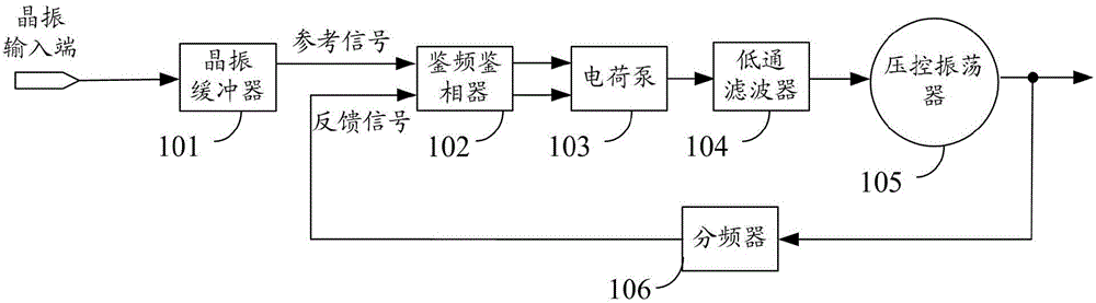
[0037] Figure 1A Is a schematic structural diagram of a phase-locked loop provided by an embodiment of the present invention, such as Figure 1A As shown, the phase locked loop may include a crystal oscillator buffer 101, a frequency discriminator 102, a charge pump 103, a low-pass filter 104, a voltage-controlled vibrator 105, and a frequency divider 106. Wherein, the crystal oscillator buffer 101 is used to buffer the crystal oscillator signal input from the crystal oscillator input terminal to generate a reference signal, and output the reference signal to the frequency discriminator 102, and the frequency discriminator 102 is used to detect the reference signal. The phase difference between the signal and the feedback signal, and output a pu...


PUM


Abstract

The invention discloses a locked detecting circuit, a method and a phase-locked circuit. The locked detecting circuit is respectively connected with a reference signal input terminal and a feedback signal input terminal of a phase-locked loop, and a controller. The locked detecting circuit comprises a phase comparison circuit and a state detection circuit. The phase comparison circuit is used for receiving reference signals from a reference signal input terminal of the phase-locked loop, receiving feedback signals from a feedback signal input terminal of the phase-locked loop, and receiving operation mode signals from the controller. Besides, phase comparison circuit is also able to generate comparison signals based on the reference signals, the feedback signals, and the operation mode signals. The state detection circuit is used for acquiring clock signals and comparing the clock signals, detecting the operation status of the phase-locked loop. The locked detecting circuit has a simple structure.

Description

technical field [0001] The invention relates to the field of communication technology, in particular to a lock detection circuit, a method and a phase lock circuit. Background technique [0002] A phase-locked loop is a closed-loop control circuit that can keep the output feedback signal and the input reference signal at the same frequency and constant phase difference under normal working conditions (that is, in the locked state). It is generally used in broadcasting, communication, frequency Synthesis and clock synchronization and other technical fields. The traditional phase-locked loop is generally composed of frequency and phase detectors, charge pumps, loop filters, voltage-controlled oscillators and frequency dividers. Because when the phase-locked loop is in an abnormal working state (i.e. out-of-lock state), it is easy to cause the system using the phase-locked loop to break down, so a special lock detection circuit is needed to determine the working state of the p...

Claims


Application Information

Patent Timeline
IPC IPC(8): H03L7/18
CPCH03L7/18H03L2207/14
Inventor 尤琳闵卿黄兆磊
Owner HUAWEI TECH CO LTD
Why Eureka
Try Eureka