
Continuous casting tundish

A continuous casting tundish and tundish technology, which is applied in casting equipment, casting molten material containers, manufacturing tools, etc., can solve the inconsistency of heat loss at multiple water outlets, filter and remove impurities from molten steel that has not been injected, and reduce the use of tundishes Life and other issues, to improve product quality, avoid loss of raw materials, prolong life

Inactive Publication Date: 2017-02-01
WUHAN WINNING TECH
View PDF8 Cites 6 Cited by
  • Summary
  • Abstract
  • Description
  • Claims
  • Application Information

AI Technical Summary

Problems solved by technology

[0003] The structure of the currently used continuous casting tundish can only be divided, and has no function of filtering and removing impurities for the injected molten steel. In addition, the molten steel injected into the tundish cannot be evenly divided from multiple outlets, resulting in multiple The degree of heat loss of each water outlet is inconsistent. After a period of use, the water outlet located in the middle of the bottom of the tundish will burn out due to heat damage, and water leakage will occur, which not only causes waste of raw materials, but also poses a major safety hazard to safe production. Hidden dangers greatly reduce the service life of the tundish and increase the production cost

Method used


Image

  • Continuous casting tundish
  • Continuous casting tundish
  • Continuous casting tundish

Examples


Embodiment Construction

[0033] The principles and features of the present invention are described below in conjunction with the accompanying drawings, and the examples given are only used to explain the present invention, and are not intended to limit the scope of the present invention.

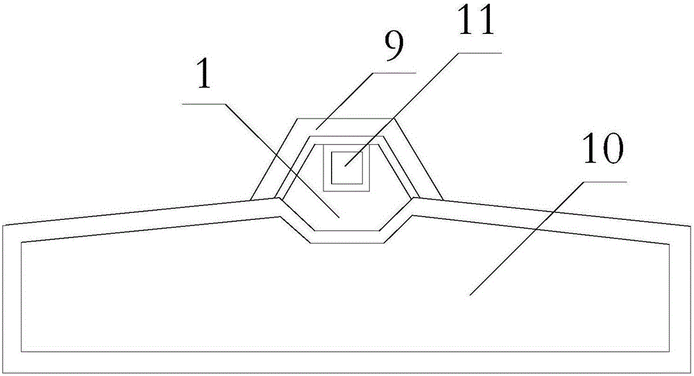
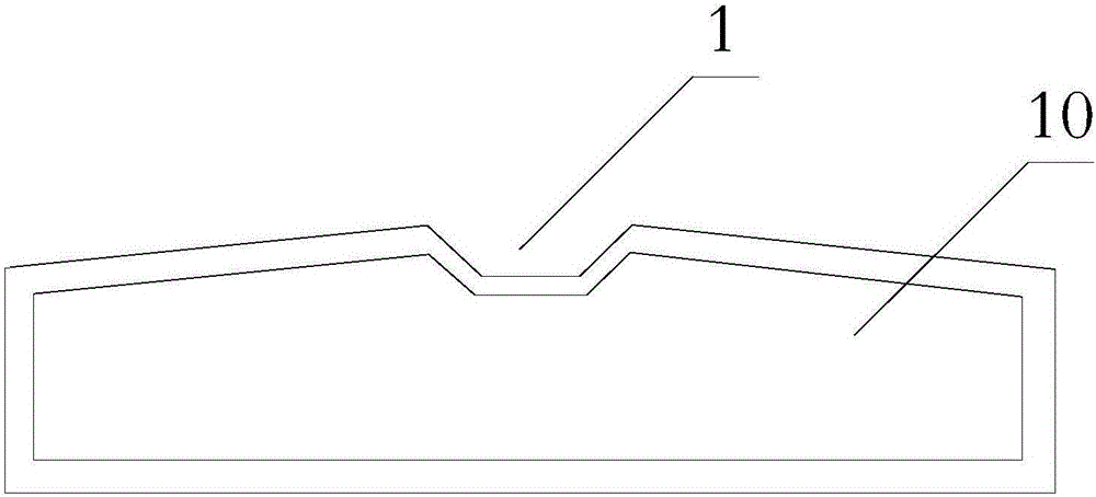
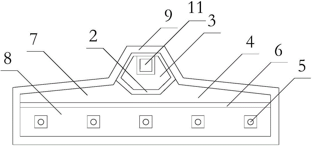
[0034] like Figures 1 to 4 As shown, a continuous casting tundish, the tundish is hollow and three-dimensional, the upper end of the tundish is provided with a feed port 1, and a filter wall 2 is vertically provided in the tundish, and the filter wall 2 Divide the internal space of the tundish into a blanking area 3 and a splitting area 4, and the feed inlet 1 is located directly above the blanking area 3, and the bottom surface of the tundish is located in the splitting area 4 There are multiple diversion ports 5 .

[0035] In the tundish, a flow equalizing plate 6 is vertically arranged in the flow splitting area 4, and the flow equalizing plate 6 divides the flow splitting area 4 into a flow storage area 7 and ...


PUM


Abstract

The invention relates to a continuous casting tundish. The tundish is in a hollow three-dimensional shape. A feeding inlet is formed in the upper end of the tundish. A filter wall is vertically arranged inside the tundish. The internal space of the tundish is partitioned into a discharging region and a flow distribution region through the filter wall. The feeding inlet is located over the discharging region. A plurality of flow distribution openings are formed in the portion, located in the flow distribution region, of the bottom face of the tundish. A flow equalizing plate is vertically arranged at the portion, located in the flow distribution region, inside the tundish. The flow distribution region is partitioned into a flow storage region and a flow equalizing region through the flow equalizing plate. The flow storage region is located between the discharging region and the flow equalizing region. All the flow distribution openings are formed in the bottom of the tundish and located inside the flow equalizing region. According to the continuous casting tundish, molten steel injected from the feeding inlet can be filtered through the filter wall and subjected to flow equalizing treatment through the flow equalizing plate, the molten steel can uniformly flows to external crystallizers in a distributed mode through the multiple flow distribution openings, uniform consumption is achieved at all the flow distribution openings, the overall service life of the tundish is greatly prolonged, and the production cost is lowered.

Description

technical field [0001] The invention relates to the technical field of iron and steel smelting, in particular to a continuous casting tundish. Background technique [0002] The tundish is a refractory container used in short-process steelmaking. It first receives the molten steel poured from the ladle, and then distributes it to each crystallizer through the tundish nozzle. The tundish is the middle link of the steelmaking production process, and it is also the transition point from intermittent operation to continuous operation. As a metallurgical reactor, the tundish is an important part of improving steel production and quality. [0003] The structure of the currently used continuous casting tundish can only be divided, and has no function of filtering and removing impurities for the injected molten steel. In addition, the molten steel injected into the tundish cannot be evenly divided from multiple outlets, resulting in multiple The degree of heat loss of each water ou...

Claims


Application Information

Patent Timeline
IPC IPC(8): B22D41/00B22D1/00
CPCB22D41/00B22D1/00
Inventor 林先桥冯广雷青云丁良盛康斌峰
Owner WUHAN WINNING TECH
Learn More