Eureka AIR delivers breakthrough ideas for toughest innovation challenges, trusted by R&D personnel around the world.

Metal member and plastic jointing method and structure

A technology of metal components and joint structures, applied in chemical instruments and methods, metal layered products, layered products, etc., can solve problems such as insufficient joint force, inability to embed, small pore size, etc., to maintain strength and integrity, Increased bonding strength, light weight effect

Inactive Publication Date: 2017-02-01
林暄智 +1
View PDF0 Cites 3 Cited by
  • Summary
  • Abstract
  • Description
  • Claims
  • Application Information

AI Technical Summary

Problems solved by technology

[0004] However, there are the following problems in the existing joints of metal components and plastics. Whether it is electroplating or etching, the processing speed is quite slow and tedious, which does not meet any economic benefits, and the liquid used in these electroplating or etching will not be used in the future. will cause serious environmental problems
The holes formed by the chemical etching process are not only small in diameter but also quite shallow in depth, resulting in the inability to effectively improve the bonding strength of metal components and plastics, and can only be used for small-area partial bonding or products with low bonding strength.
Each hole is formed independently. When the plastic enters the hole, it is often unable to be embedded due to poor exhaust, resulting in insufficient bonding force and inability to effectively bond with metal components in a large area.

Method used

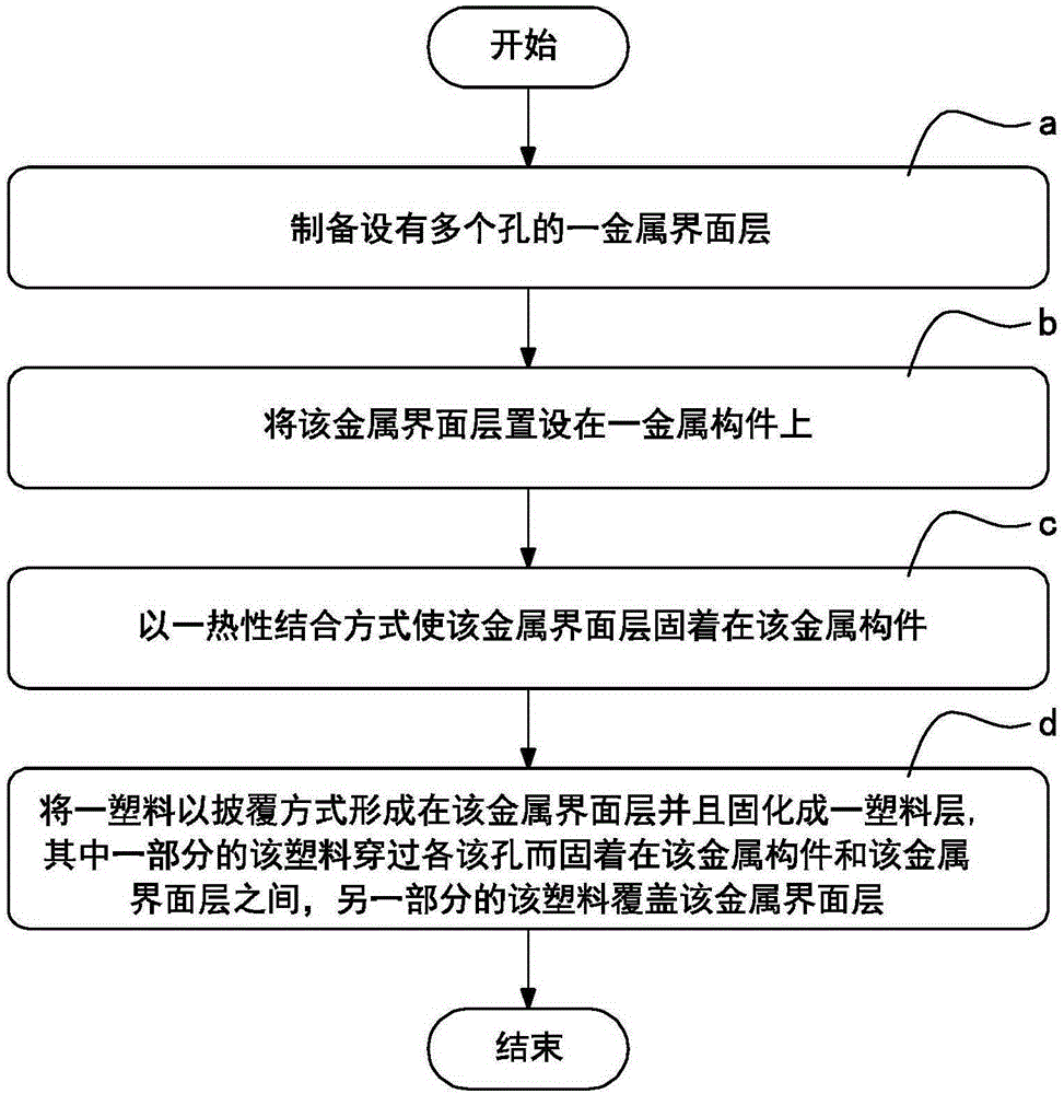

Image

  • Metal member and plastic jointing method and structure
  • Metal member and plastic jointing method and structure
  • Metal member and plastic jointing method and structure

Examples


Embodiment Construction

[0034] The detailed description and technical content of the present invention are described below in conjunction with the accompanying drawings. However, the accompanying drawings are only for reference and description, and are not intended to limit the present invention.

[0035] see figure 1 and Figure 5 As shown, the present invention provides a metal component and a plastic bonding method and structure thereof, wherein the method steps include:

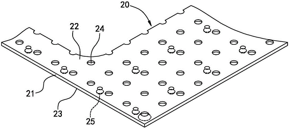
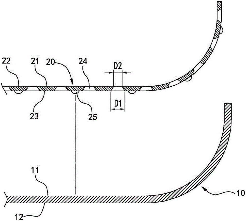
[0036] a) Preparation of a metal interface layer 20 with holes; see figure 2 and image 3 As shown, the metal interface layer 20 can be a light metal material such as aluminum alloy, magnesium alloy or aluminum-magnesium alloy. The metal interface layer 20 in this embodiment is a thin plate with a thickness ranging from 0.05 to 0.2 millimeters (mm). The metal interface layer 20 has a plate 21, an upper surface 22 is formed on the upper side of the plate 21, and the lower side of the plate 21 is formed at a position facing aw...


PUM

PropertyMeasurementUnit
Thicknessaaaaaaaaaa
Thicknessaaaaaaaaaa
Thicknessaaaaaaaaaa

Abstract

The invention discloses a metal member and plastic jointing method and structure. The jointing structure comprises a metal member, a metal interface layer and a plastic layer, and the metal member has a first surface; the metal interface layer has an upper surface and a lower surface formed on the back of the upper surface, the lower surface is arranged corresponding to the first surface, the metal interface layer is provided with a plurality of holes, and all the holes are mutually connected at one side of the lower surface; and the plastic layer is laid corresponding to the metal interface layer, one part of the plastic layer traverses through the holes and is anchored between the first surface and the lower surface, and the other part of the plastic covers the upper surface of the metal interface layer. The method and the structure have the advantages of improvement of the metal member and plastic layer jointing firmness, simplicity of the process, and shortening of the making time.

Description

technical field [0001] The invention relates to a composite material bonding technology, in particular to a metal component and plastic bonding method and its structure. Background technique [0002] With the continuous progress and development of science and technology, the application of composite materials in various products has become more and more common, such as mobile phone, tablet computer, notebook computer casing and mechanism accessories; fan blades, automobile and motorcycle spare parts, medical equipment , home appliance shells or spare parts, safety helmets; exterior sheet parts and internal structural parts of automobiles and motorcycles, internal and external parts of aircraft, propellers, general hull structural parts, military helmets, bulletproof parts, sanitary equipment, building materials, etc. The finished products produced by it not only have many advantages such as light weight, thinning, good appearance and texture, but also can effectively reduce ...

Claims


Application Information

Patent Timeline
IPC IPC(8): B29C65/02B29C65/08B32B15/04B32B7/10
Inventor 林暄智李峻丞
Owner 林暄智
Why Eureka
Eureka Blog
Learn More