
Composite high earth-rock dam

A high earth-rock dam and composite technology, applied in the direction of dams, barrages, barrages, etc., can solve the problems of large core wall engineering, unfavorable dam slope stability, and poor anti-seepage safety, so as to reduce pollution and improve anti-seepage. seepage effect, environmental protection effect

Inactive Publication Date: 2017-02-01
CHINA HYDROELECTRIC ENGINEERING CONSULTING GROUP CHENGDU RESEARCH HYDROELECTRIC INVESTIGATION DESIGN AND INSTITUTE
View PDF6 Cites 5 Cited by
  • Summary
  • Abstract
  • Description
  • Claims
  • Application Information

AI Technical Summary

Problems solved by technology

[0003] For earth-rock dams with soil core walls, the downstream slope ratio of the soil core walls is generally 1:2.0 to 1:3.0. Especially for earth-rock dams with high soil core walls, the width of the soil core wall is wide and the section of the core wall is large, which is not conducive to the stability of the dam slope. ; The core wall has a large amount of engineering, a large amount of soil materials, high cost, and takes up a lot of cultivated land, which is not conducive to environmental protection
For earth-rockfill dams with asphalt cores, especially high asphalt core dams, in order to meet the anti-seepage requirements of the dam, wider asphalt cores are often used, and the asphalt core is the only anti-seepage barrier of the dam body. No other anti-seepage protection measures, poor anti-seepage safety

Method used


Image

  • Composite high earth-rock dam

Examples


Embodiment Construction

[0012] The present invention will be further described below in conjunction with accompanying drawing.

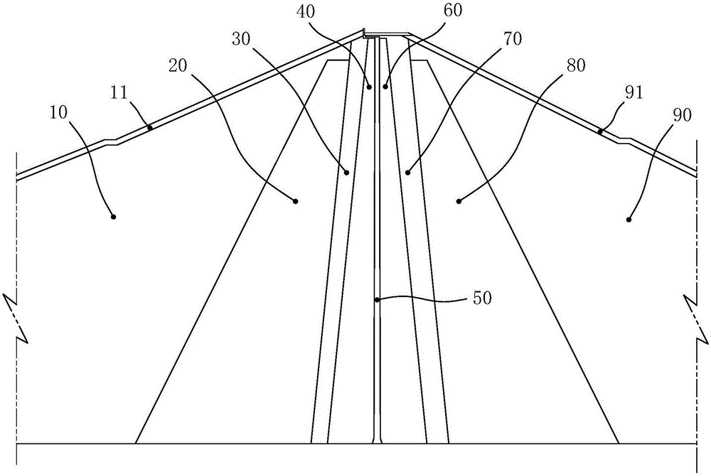
[0013] Such as figure 1 As shown, the composite high earth-rockfill dam includes an asphalt core 50, and an upstream rockfill area 10, an upstream transition layer 20, an upstream filter layer 30, and an upstream soil core that are sequentially arranged on the upstream side of the asphalt core 50 along the flow direction. 40, and the downstream soil core 60, the downstream filter layer 70, the downstream transition layer 80 and the downstream rockfill area 90 which are sequentially arranged on the downstream side of the asphalt core 50 along the flow direction. Wherein, an upstream slope protection structure 11 is provided on the surface of the upstream rockfill area 10 , and a downstream slope protection structure 91 is provided on the surface of the downstream rockfill area 90 . In order to ensure the anti-seepage safety of the dam body and the stability of the dam slope...


PUM


Abstract

The invention belongs to the field of water conservancy and hydropower engineering, and particularly discloses a composite high earth-rock dam low in cost and good in anti-seepage effect. The composite high earth-rock dam comprises an asphalt core wall, an upstream rockfill area, an upstream transition layer, an upstream reversed filter layer, an upstream earth core wall, a downstream earth core wall, a downstream reversed filter layer, a downstream transition layer and a downstream rockfill area, wherein the upstream rockfill area, the upstream transition layer, the upstream reversed filter layer and the upstream earth core wall are sequentially arranged on the upstream side of the asphalt core wall along the water flow direction, and the downstream earth core wall, the downstream reversed filter layer, the downstream transition layer and the downstream rockfill area are sequentially arranged on the downstream side of the asphalt core wall along the water flow direction. The upstream earth core wall and the downstream earth core wall are arranged on the upstream side and the downstream side of the asphalt core wall correspondingly to form a composite core wall structure, on the premise of guaranteeing stability and safety of a dam body, the use level of anti-seepage earth materials and asphalt materials can be reduced, and the engineering investment is reduced; and the upstream earth core wall and the downstream earth core wall can have the repair function on construction defects existing on the asphalt core wall, the anti-seepage effect of the asphalt core wall is effectively improved, and the anti-seepage safety of the dam body is greatly improved.

Description

technical field [0001] The invention belongs to the field of water conservancy and hydropower engineering, and in particular relates to a composite high earth-rock dam. Background technique [0002] Soil core and asphalt core are two common core structures for earth-rock dams. The width of these two core walls is determined according to the allowable seepage gradient of the core wall, and considering the requirements of seismic crack resistance and mechanical construction of the core wall. The section of the soil core wall gradually widens from top to bottom, the top width is generally not less than 3m, and the bottom width is generally not less than 1 / 4 of the water head. The top width of the asphalt core wall is generally not less than 40cm, and the bottom width is 1 / 70 to 1 / 130 of the dam height. [0003] For earth-rock dams with soil core walls, the downstream slope ratio of the soil core walls is generally 1:2.0 to 1:3.0. Especially for earth-rock dams with high soil ...

Claims


Application Information

Patent Timeline
Patent Type & Authority Applications(China)
IPC IPC(8): E02B7/06
CPCE02B7/06
Inventor 王党在叶发明余学明王晓东冉从勇
Owner CHINA HYDROELECTRIC ENGINEERING CONSULTING GROUP CHENGDU RESEARCH HYDROELECTRIC INVESTIGATION DESIGN AND INSTITUTE
Learn More