
A compressed air energy storage device based on constant temperature control
A compressed air energy storage and constant temperature control technology, which is applied to pump devices, liquid variable capacity machines, pumps, etc., can solve the problems of low energy storage utilization efficiency and incomplete utilization of compressed air potential energy, and achieve high energy storage utilization. , simple structure, good safety effect
- Summary
- Abstract
- Description
- Claims
- Application Information
AI Technical Summary
Problems solved by technology
Method used
Image

Examples
Embodiment Construction
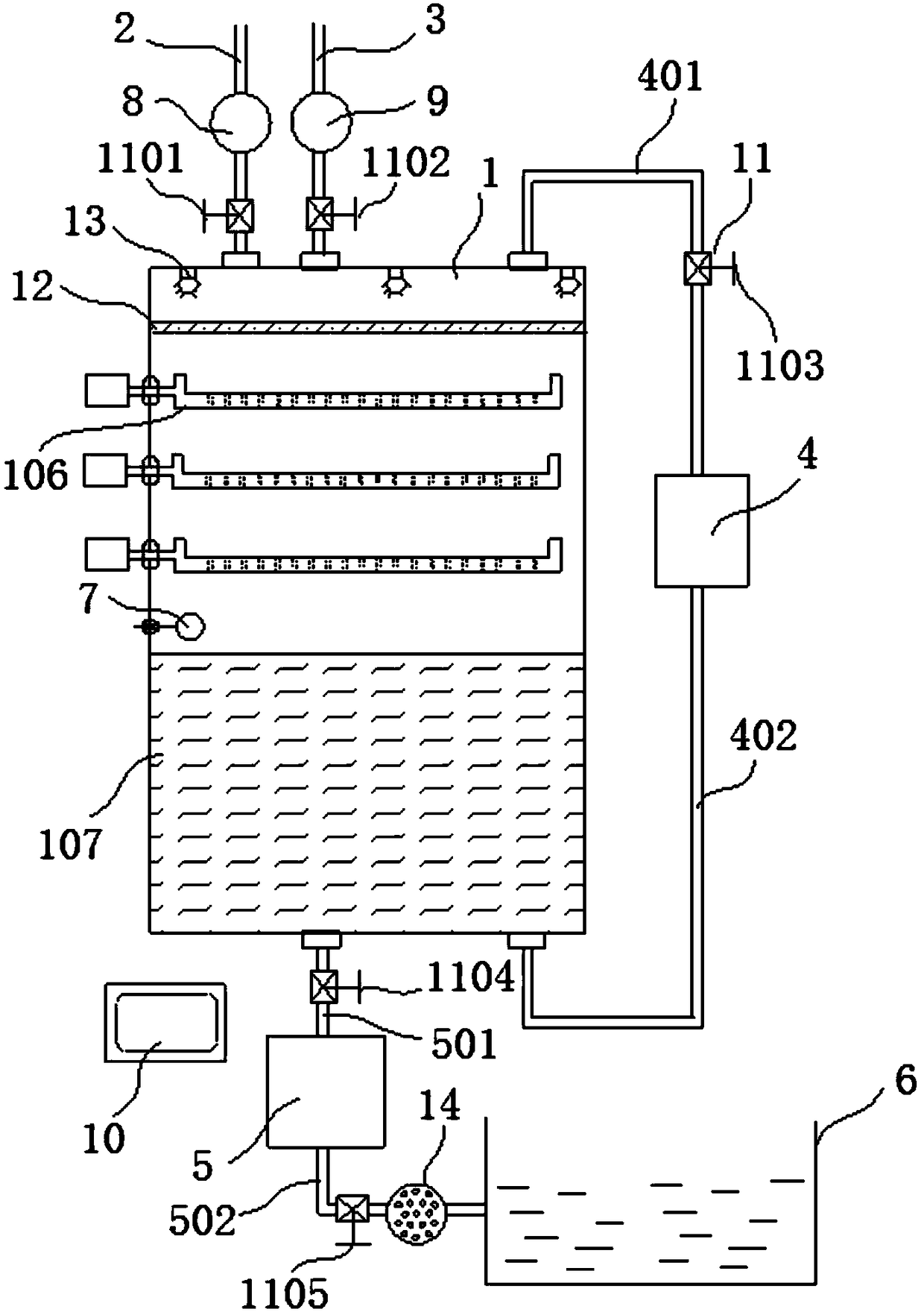
[0032] like figure 1 As shown, the compressed air energy storage device based on constant temperature control of the present invention includes:
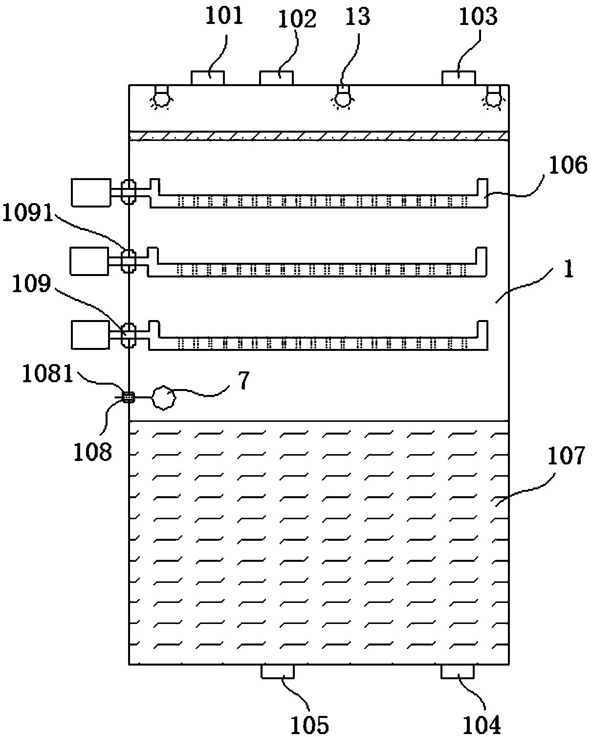
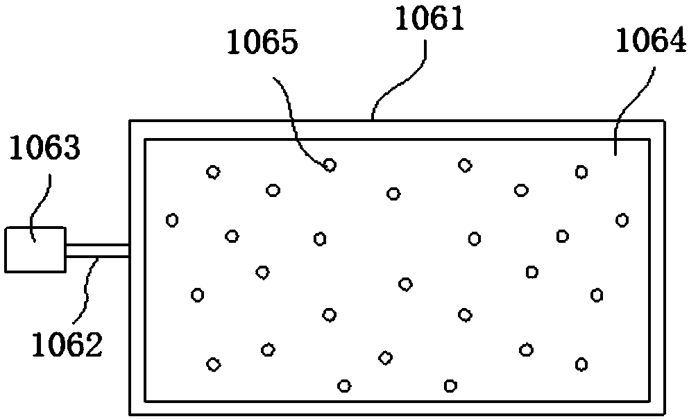
[0033] Liquid piston 1, such as figure 2 As shown, the upper part of the liquid piston 1 is provided with a first port 101, the second port 102, and the third port 103, and the lower part of the liquid piston 1 is provided with a fourth port 104 and a fifth port 105. A plurality of rotatable liquid storage plates 106 are arranged above the inside of the piston 1 , and multi-layer packing 107 is arranged under the inside of the liquid piston 1 . In this example, if image 3 As shown, the rotatable liquid storage plate 106 includes a rotating plate 1061, a rotating shaft 1062, and a rotating motor 1063. The first end of the rotating shaft 1062 is connected to the rotating plate 1061, and the second end of the rotating shaft 1062 The end passes through the side wall of the liquid piston 1 and is connected to the rotary motor 1063 ,...
PUM
 Abstract
Description
Claims
Application Information