A disc spring damper capable of adjusting early stiffness

A disc spring and damper technology, applied in the direction of spring/shock absorber, shock absorber, shock absorber, etc., can solve the problems of increased length of the damper, deformation of the disc spring, waste, etc. Resonance, the effect of reducing the cost of isolation

Active Publication Date: 2018-05-11
湖州优研知识产权服务有限公司
View PDF7 Cites 0 Cited by
  • Summary
  • Abstract
  • Description
  • Claims
  • Application Information

AI Technical Summary

Problems solved by technology

[0006] 1. The load connecting rod is kept balanced under the joint action of two sets of disc springs. Although the pre-tightening force of the two sets of disc springs can be adjusted, no matter how it is adjusted, the force of the two sets of disc springs on the load connecting rod will The acting forces are a set of equal and opposite forces, and simply applying any external force on the load connecting rod will break this balance and deform the two sets of disc springs, so the damper described cannot preset the early stiffness ;
[0007] 2. The damping coefficient of the disc spring is changed by preloading two sets of disc springs. This change is very limited, which leads to a small adjustment range of the equivalent stiffness of the damper, which often cannot meet the frequency requirements of building isolation;
[0008] 3. In this invention, two sets of disc springs must be used together to provide damping when the damper is under compression or tension load. This not only causes a certain amount of waste, but also greatly increases the length of the damper, which is not suitable for some Use where the installation space is tight
It can be seen that although the stiffness of the spring in the patent application scheme can be changed, the effective working length of the spring is not only significantly shortened, but also can only be compressed for energy consumption and vibration reduction, and cannot be stretched for energy consumption and vibration reduction.

Method used


Image

  • A disc spring damper capable of adjusting early stiffness
  • A disc spring damper capable of adjusting early stiffness
  • A disc spring damper capable of adjusting early stiffness

Examples


example 1

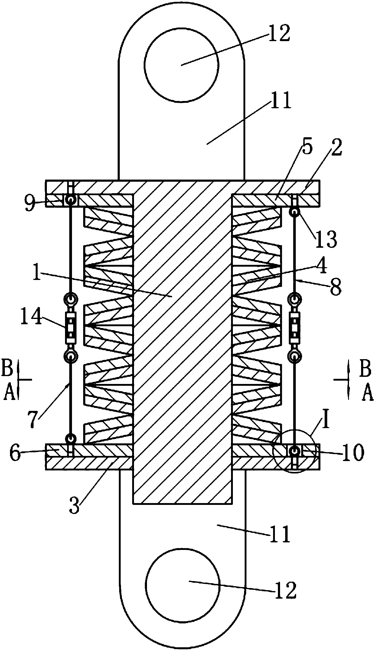
[0033] see figure 1 with 4 , the disc spring damper that can adjust the early stiffness in this example is a damper that can be used for seismic reinforcement of building structures. The damper includes a disc-shaped upper end plate 2 and a lower end plate 3. Disc spring group 4, wherein upper end plate 2 is provided with guide rod 1, and this guide rod 4 passes through the lower end plate 3 downwards along the center hole of disc spring group 4; Described disc spring group 4 consists of sixteen pieces Disc springs are superimposed, and the lower end plate 3 is in dynamic cooperation with the guide rod 1 .

[0034] see figure 1 with 4 , the upper surface of the upper end plate 2 and the lower surface of the lower end plate 3 are respectively provided with two connecting ear plates 11 with hinged holes 12 . And the distance between the hinged hole 12 on the lower end plate 3 and the lower end plate 3 is greater than the length of the end of the guide rod 1 passing through...

example 2

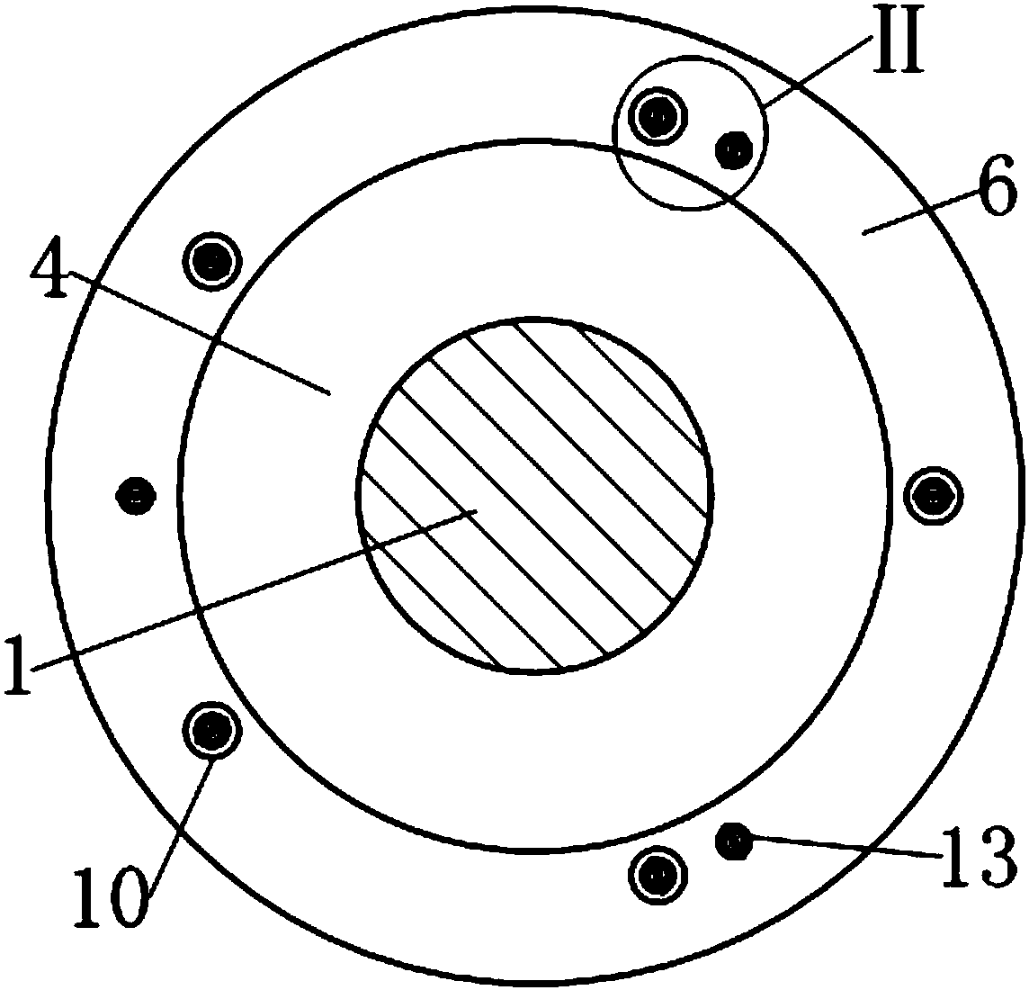
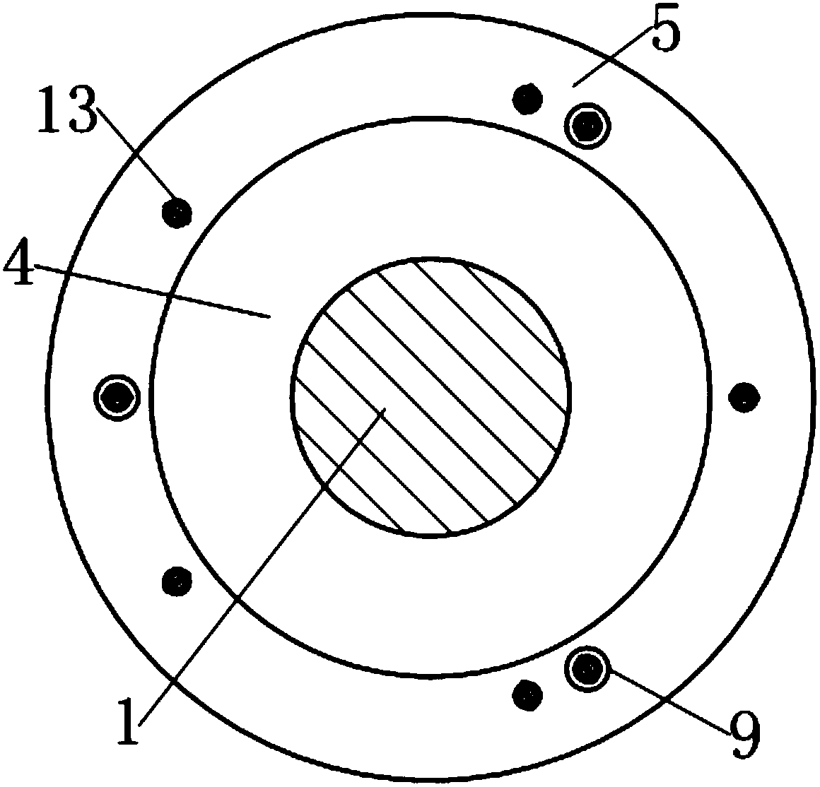
[0042] see Figure 7-10 , compared with Example 1, this example has the following main differences:

[0043] 1. Both the first group of preloaded steel cables 8 and the second group of preloaded steel cables 7 are composed of three preloaded steel cables; The middle of each preloaded steel cable.

[0044] 2. In order to prevent dust and other sundries from falling on the disc spring group 4 and affect the normal operation of the damper, a layer of rubber protective sleeve 15 is wrapped on the outside of the back pressure device. The two ends of the protective sleeve 15 are respectively connected to the first floating The outer peripheral surfaces of the pressing plate 6 and the second floating pressing plate 5 are glued together. The length of the sheath 15 is greater than the distance between the upper surface of the upper end plate 2 and the lower surface of the lower end plate 3, so as not to affect the work of the damper.

[0045] The implementation method of this examp...

example 3

[0047] see Figures 11 to 13 , the disc spring damper that can adjust the early stiffness in this example is a kind of vibration isolation device (also called seismic isolation support) that can be used for vertical vibration isolation of buildings. Compared with Example 2, this example mainly has the following differences :

[0048] 1. As a vibration isolation support, in order to facilitate installation, in this example, the connecting lug plate set on the upper end plate 2 in Example 2 is omitted, and the edge of the upper end plate 2 is extended radially outward, and evenly arranged at the edge Connect the bolt holes 17.

[0049] 2. The connecting lugs provided on the outside of the lower end plate 3 in Example 2 are omitted, and the lower end plate 3 is extended axially downward from the edge and then radially outward to form the base of the damper, and the connection is evenly arranged on the edge Bolt hole 17; wherein the length extending axially downward is greater t...


PUM


Abstract

The invention relates to a disc spring damper with the adjustable initial rigidity. The damper is characterized in that a counter pressure device is arranged between two end plates and comprises two pre-compression steel wire rope units and two floating compression plates, each pre-compression steel wire rope unit comprises at least three pre-compression steel wire ropes, and the two floating compression plates are arranged on guide rods between the end plates and a disc spring set in a sleeving mode respectively; the two pre-compression steel wire rope units are symmetrically distributed around the disc spring set around the axes of the guide rods in a linear mode, one end of each pre-compression steel wire rope unit is fixed to one floating compression plate, and the other end of each pre-compression steel wire rope unit penetrates through the other floating compression plate to be fixed to the end plate adjacent to the floating compression plate; the middle of each pre-compression steel wire rope is connected to a rigging turnbuckle in series; and when the two pre-compression steel wire rope units are tensioned, the disc spring set can be always clamped between the two floating compression plates.

Description

technical field [0001] The present invention relates to shock absorbing devices, and in particular to dampers using disc springs. Background technique [0002] A damper is a shock-absorbing device that consumes motion energy by providing motion resistance. The use of dampers to absorb shock is a traditional technology widely used in industries such as aerospace, aviation, military industry, guns and automobiles. Since the 1970s, people have gradually applied the technology of using dampers to absorb and absorb shocks in structural engineering such as buildings, bridges, and railways. Disc spring dampers are widely used in various building anti-seismic structures due to their high impact resistance, low cost and good shock absorption effect. [0003] People pursue a comprehensive anti-seismic performance that combines "resistance" and "consumption" for the design of buildings, especially high-rise buildings, that is, under the action of weak wind vibration and small earthqu...

Claims


Application Information

Patent Timeline
Patent Type & Authority Patents(China)
IPC IPC(8): F16F7/104
CPCF16F7/104
Inventor 沈珊胡济福胡济全
Owner 湖州优研知识产权服务有限公司
Why Eureka
Try Eureka