Adaptive microphone array calibration method based on variable step NLMS algorithm

A technology of a microphone array and a calibration method, applied in the field of signal processing, can solve problems such as attenuation or distortion of received signals, and achieve the effects of calibration optimization and calibration accuracy improvement.

Inactive Publication Date: 2017-02-01
SYSU CMU SHUNDE INT JOINT RES INST +1
View PDF3 Cites 6 Cited by
  • Summary
  • Abstract
  • Description
  • Claims
  • Application Information

AI Technical Summary

Problems solved by technology

[0006] The purpose of the present invention is to realize the adaptive calibration of the received signal of the microphone array, solve the problem that the beamformer will seriously attenuate or distort the received signal due to the mismatch problem of the microphone, and at the same time, the algorithm provided by the present invention enables the output signal to reach Faster error convergence and smaller distortion errors

Method used


Image

  • Adaptive microphone array calibration method based on variable step NLMS algorithm
  • Adaptive microphone array calibration method based on variable step NLMS algorithm
  • Adaptive microphone array calibration method based on variable step NLMS algorithm

Examples


Embodiment 1

[0035] Such as Figure 4 As shown, the microphone array adaptive calibration method based on variable step size NLMS algorithm provided by the present invention comprises the following steps:

[0036] S1. Select the output signal x of the nth group of microphone array N microphones 0 (n), x 1 (n), x 2 (n),...,x N-1 (n) as a signal to be calibrated;

[0037] S2. Select the nth group output signal x of one of the microphones i (n) input to the delay filter for time delay compensation, and output signal d(n) as a reference signal after compensation is completed;

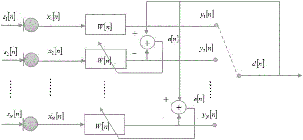
[0038] S3. will output signal x 0 (n), x 1 (n), x 2 (n),...,x N-1 (n) respectively input to the calibration filter W 0 [n], calibration filter W 1 [n], ..., calibration filter W N-1 [n] for calibration, calibration filter W 0[n], calibration filter W 1 [n], ..., calibration filter W N-1 [n] Output the calibrated output signal y respectively 0 (n), y 1 (n),...,y N-1 (n);

[0039] S4. Let the calibratio...

Embodiment 2

[0046] In this embodiment, on the basis of embodiment 1, specific experiments are carried out. In the experiment, N=8 microphones are taken to form a microphone array according to a certain topology, such as figure 1 As shown, after the voice signal s(n) from the sound source is received by the microphone, the microphone outputs the signal x i (n) as input to the correction filter. In the experiment of this embodiment, one of the output signals of one of the eight microphones is selected to be input to the delay filter for time delay compensation, and the reference signal d(n) is output after the compensation is completed.

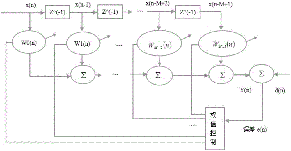
[0047] figure 2 A diagram of the implementation process for signal calibration, figure 2 In the method provided in this embodiment, the calibration signal output each time is compared with the reference signal, and the principle of adaptive calibration is based on the minimum error value between the two, and the filter coefficients are continuously up...


PUM


Abstract

The invention provides a method. According to the method, coefficients of a calibration filter are updated according to calibration results after each calibration, so the calibration filter can excellently fit characteristics of output signals, accuracy of calibration is improved compared with the prior art, as the coefficients of the calibration filter change in a mode of adapting to the characteristics of the output signals in a whole calibration process, the calibration method provided can excellently adapt to relatively large change of output characteristics of a microphone array caused by aging or environment change factors of the microphone array, and the output signals can be effectively calibrated, moreover, in the calibration process, the coefficients of the calibration filter are adjusted through introducing a variable step NLMS algorithm, more rapid error convergence speed and smaller distortion error effects on the output signals can be realized through the variable step NLMS algorithm, and calibration optimization is realized.

Description

technical field [0001] The present invention relates to the technical field of signal processing, and more specifically, to a microphone array adaptive calibration method based on a variable step size NLMS algorithm. Background technique [0002] Microphone array speech applications have been studied for over two decades. But still only a very small number of products use microphone arrays, and the vast majority of products use a single microphone. When a single microphone receives a voice signal, the quality of the signal received by a single microphone will be affected by factors such as the influence of multiple sound sources and environmental noise, as well as the mobility of the sound source and the multipath reflection and reverberation of various other sounds in the room. , resulting in a serious deterioration in the quality of voice communication. Based on the above various shortcomings of receiving signals with a single microphone, the prior art proposes to use a ...

Claims


Application Information

Patent Timeline
Patent Type & Authority Applications(China)
IPC IPC(8): G10L21/0216
CPCG10L21/0216G10L2021/02166
Inventor 谭洪舟何粤李宇
Owner SYSU CMU SHUNDE INT JOINT RES INST
Why Eureka
Try Eureka