Automatic adjustment method for dead-time compensation voltage value of motor driver

A motor driver and dead zone compensation technology, which is applied in the direction of controlling electromechanical brakes, controlling generators, motor generators, etc., can solve problems such as different and no real-time online detection, and achieve improved smoothness, steady-state and dynamic operation effects Superior, improved shock and distortion effects

Active Publication Date: 2017-02-01
SHANGHAI STEP ELECTRIC +1
View PDF4 Cites 3 Cited by
  • Summary
  • Abstract
  • Description
  • Claims
  • Application Information

AI Technical Summary

Problems solved by technology

First of all, this look-up table dead zone compensation method has no real-time online detection of whether the dead zone compensation voltage value is reasonable. Whether the dead zone compensation value is reasonable or not depends entirely on whether the pre-made table is reasonable. It is related to the root mean square value of the current, it is also related to the electrical characteristics of the motor itself, and it is related to the rotation speed of the motor. In other words, different motors are most suitable under the same root mean square value of current under different speed conditions. The value of the dead zone compensation voltage is different

Method used


Image

  • Automatic adjustment method for dead-time compensation voltage value of motor driver
  • Automatic adjustment method for dead-time compensation voltage value of motor driver
  • Automatic adjustment method for dead-time compensation voltage value of motor driver

Examples


Embodiment 1

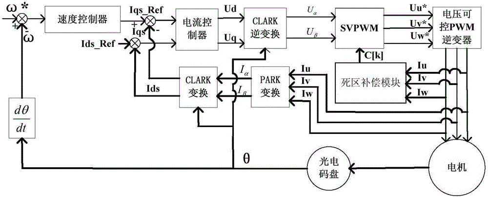
[0032] The automatic adjustment method of the dead-time compensation voltage value of the motor driver according to Embodiment 1 includes the following steps:

[0033] Step a, select at least 5 numbers c[0], c[1], c[2],...c[n] as the first screening dead zone compensation voltage value, n≥4;

[0034] Step b, the motor driver drives the asynchronous motor to rotate according to the selected first dead zone compensation voltage value c[0];

[0035] Step c, every preset time period T s Sampling the stator current I of the motor u once, and recorded separately as x u (k), where k=0,1,2,…2 N -1, N is a positive integer, M=2 N , f is the frequency of the stator current of the asynchronous motor; a total of 2 samples N end sampling after the number of times;

[0036] Step d, the stator current sampling value array x u (k) Perform Fourier transform to obtain the harmonic coefficient array X in the frequency domain u (k), where k=0,1,2,…2 N -1; Calculate the array number k c...

Embodiment 2

[0059] The method steps of Example 2 are similar to those of Example 1. The main difference is that Example 2 has been screened twice, while Example 2 has only been screened once. Therefore, the identification accuracy of Example 1 is better than that of Example 2, but The recognition speed of Example 2 is faster than that of Example 1.

[0060] The automatic adjustment method of the dead-time compensation voltage value of the motor driver according to Embodiment 1 includes the following steps:

[0061] Step a, select at least 5 numbers c[0], c[1], c[2],...c[n] as the first screening dead zone compensation voltage value, n≥4;

[0062] Step b, the motor driver drives the asynchronous motor to rotate according to the selected first dead zone compensation voltage value c[0];

[0063] Step c, every preset time period T s Sampling the stator current I of any phase of the motor u once, and recorded separately as x u(k), where k=0,1,2,…2 N -1, N is a positive integer, M=2 N , ...


PUM


Abstract

Disclosed is an automatic adjustment method for a dead-time compensation voltage value of a motor driver. The automatic adjustment method comprises the steps of at least selecting five numbers, including c[0], c[1] until c[n] to be used as primary screening dead-time compensation voltage values; driving an asynchronous motor to rotate according to c[0]; sampling a stator current Iu once every a preset time period; obtaining a harmonic coefficient array Xu(k) of a frequency domain; calculating a ratio A5[0] of five-order harmonic coefficient to fundamental wave harmonic coefficient and a ratio A7[0] of seven-order harmonic coefficient to the fundamental wave harmonic coefficient separately, and enabling A5[0] and A7[0] to be summed to obtain A[0]; deducting the rest by analogy, obtaining A[1] until A[n]; performing comparison on A[0] until A[n], taking two primary screening dead-time compensation voltage values corresponding to two smallest values therebetween as dead-time compensation voltage preferred values number 0 which is C-[0] and number 1 which C-[1]; then at least selecting five numbers, including c*[0], c*[1] until c*[j], between C-[0] and C-[1] to be used as secondary screening dead-time compensation voltage values; driving the asynchronous motor to rotate according to c*[0] until c*[j], and obtaining A*[0] until A*[j]; and performing comparison on magnitudes of A*[0] until A*[j], and taking a dead-time compensation voltage value corresponding to the smallest value as the optimal dead-time compensation voltage value. By adoption of the automatic adjustment method, the proper dead-time compensation voltage value can be automatically acquired according to the electrical characteristics of the motor.

Description

technical field [0001] The invention relates to a method for adjusting the dead zone compensation voltage value of a motor driver. Background technique [0002] Motor drives mainly include two types of equipment: frequency converters and servo drives. Frequency converters are mainly used to drive asynchronous motors and synchronous motors, while servo drives are mainly used to drive synchronous servo motors. The motor driver usually uses a three-phase bridge drive circuit. Due to the turn-on delay and turn-off delay of the power switch tubes (such as IGBT and MOSFET), in order to avoid the pass-through of the upper and lower switches of the same bridge arm, each switch must be connected. A dead time is set between the turn-on and turn-off signals of the tube. The existence of dead time makes the actual output PWM waveform of the inverter not equivalent to an ideal sine waveform, resulting in the phase current of the motor not being equivalent to an ideal sine wave, and the...

Claims


Application Information

Patent Timeline
IPC IPC(8): H02P21/14
CPCH02P21/14
Inventor 张扬金辛海
Owner SHANGHAI STEP ELECTRIC
Why Eureka
Try Eureka