Steel ladle upper water nozzle quick disassembling device, system and method

A ladle and nozzle technology is applied in the field of rapid dismantling devices for ladle nozzles, which can solve the problems of low dismantling efficiency of the nozzle on the ladle, and achieve the effects of reducing labor risks, improving coordination efficiency, and reducing labor intensity.

Inactive Publication Date: 2017-02-08
MAANSHAN IRON AND STEEL COMPANY
View PDF11 Cites 2 Cited by
  • Summary
  • Abstract
  • Description
  • Claims
  • Application Information

AI Technical Summary

Problems solved by technology

[0006] The purpose of the present invention is to overcome the problem of low removal efficiency of the ladle upper nozzle in the prior art, and provide a quick removal device, system and removal method of the ladle upper nozzle; its specific purpose is as follows:

Method used


Image

  • Steel ladle upper water nozzle quick disassembling device, system and method
  • Steel ladle upper water nozzle quick disassembling device, system and method
  • Steel ladle upper water nozzle quick disassembling device, system and method

Examples


Embodiment 1

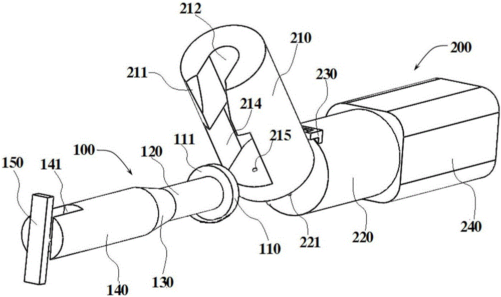
[0049] like Figure 1-Figure 5 As shown, a ladle upper nozzle removal device of the present invention includes a nozzle drawing unit 100 and a drawing drive unit 200, and the nozzle drawing unit 100 includes a pull rod stress retaining ring 110, a card slot matching a pull rod 120, a retaining The plate is connected with the pull rod 140 and the nozzle drawing baffle 150, and the force retaining ring 110 of the pull rod is connected with the baffle connection rod 140 through the slot matching pull rod 120, and the slot is matched with the pull rod 120 and the baffle is connected with the pull rod 140. A tapered connecting rod 130 is provided, and the tapered connecting rod 130 is matched with the sliding fitting arc surface 211 (such as figure 1 shown). The above-mentioned nozzle pull-out baffle 150 is arranged on the end of the baffle connection rod 140 far away from the force retaining ring 110 of the pull rod, and the nozzle pull-out baffle 150 and the baffle connection ro...

Embodiment 2

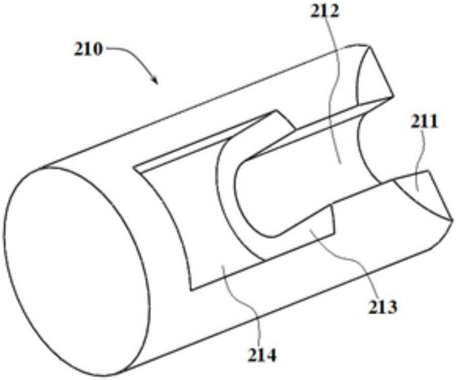
[0055] like Image 6 As shown, the tie rod force retaining ring 110 of this embodiment is provided with a tie rod limit protrusion 112, and the tie rod limit protrusion 112 is matched with the force application groove 212, and the tie rod limit protrusion 112 is used to limit the force of the pull rod The retaining ring 110 rotates relative to the pull rod engaging member 210 . And the end of the pull rod limit projection 112 close to the baffle plate connecting pull rod 140 is provided with a bump guide rod 113, and the bump guide rod 113 is used to guide the pull rod limit bump 112 into the force application groove 212, thereby limiting the force on the pull rod. The retaining ring 110 rotates relative to the tie rod fastening member 210. Because the tie rod is stressed, the retaining ring 110 is easy to rotate relative to the tie rod fastening member 210 during the force application process after the tie rod fastening member 210 cooperates. This rotation is very easy to cau...

Embodiment 3

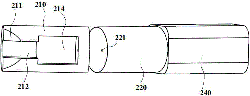
[0057] like Figure 7 As shown, the oil cylinder retraction rod 220 of this embodiment is provided with a positioning screw hole 221, the pull rod fastening member 210 is provided with a positioning matching hole 215 matching with the positioning screw hole 221, and the positioning screw 216 is matched with the positioning screw hole 221 , the positioning screw 216 passes through the positioning matching hole 215 and cooperates with the positioning screw hole 221, thereby fixing the pull rod fastening member 210 on the retractable pull rod 220 of the oil cylinder, effectively preventing the pull rod fastening when the pulling drive cylinder 240 drives the pull rod fastening member 210 The component 210 rotates relative to the fastening rotation pivot 230, so as to ensure that the pull rod fastening member 210 evenly applies a pulling force to the pull rod force retaining ring 110 to ensure the uniformity of the pulling force, thereby preventing the equipment from being damaged ...


PUM


Abstract

The invention discloses a steel ladle upper water nozzle quick disassembling device, system and method, and belongs to the technical field of steel ladle water nozzle maintenance. The steel ladle upper water nozzle quick disassembling device comprises a water nozzle drawing unit and a drawing driving unit. The water nozzle drawing unit comprises a pull rod force bearing check ring, a clamping groove matching pull rod, a baffle connecting pull rod and a water nozzle drawing baffle, wherein the pull rod force bearing check ring is connected with the baffle connecting pull rod through the clamping groove matching pull rod, and the water nozzle drawing baffle is arranged at the end, far away from the pull rod force bearing check ring, of the baffle connecting pull rod. The drawing driving unit comprises a pull rod buckling component and a drawing driving oil cylinder, wherein the pull rod buckling component and the drawing driving oil cylinder are connected in a rotating mode through a pivot, and a force application clamping groove is matched with the clamping groove matching pull rod. According to the steel ladle upper water nozzle quick disassembling device, system and method, the pull rod buckling component of the drawing driving unit and the pull rod force bearing check ring of the water nozzle drawing unit are matched with each other, the drawing driving oil cylinder can be started to apply pulling force to the pull rod force bearing check ring, and therefore a steel ladle upper water nozzle can be quickly disassembled from a water nozzle pocket block.

Description

technical field [0001] The invention relates to the technical field of ladle nozzle maintenance, more specifically, to a ladle upper nozzle quick removal device, system and removal method. Background technique [0002] The ladle hot repair operation refers to the operation of re-checking and replacing the refractory material at the nozzle part after the molten steel is poured, mainly to check the corrosion status of the ladle sliding nozzle refractory material. When it is judged that the erosion of refractory materials such as the upper nozzle, slide plate or lower nozzle of the ladle sliding nozzle is difficult to meet the requirements of continuous use, it is necessary to remove the corresponding refractory materials at the upper nozzle and replace it. [0003] Among them: the ladle sliding nozzle is an important device to control the flow of molten steel in the ladle, mainly including the upper nozzle, the upper sliding plate, the lower plate and the lower nozzle. Its wor...

Claims


Application Information

Patent Timeline
IPC IPC(8): B22D41/56
CPCB22D41/56
Inventor 刘前芝张良明解养国
Owner MAANSHAN IRON AND STEEL COMPANY
Why Eureka
Try Eureka