injection mold

A technology for injection molds and molds, applied in the field of injection molding equipment, can solve the problems affecting the quality of injection molding, waste of melt materials, and inability to ventilate smoothly, so as to prevent excessive cavity pressure, avoid material waste, and eliminate potential safety hazards. Effect

Active Publication Date: 2018-06-22
NINGBO INST OF TECH ZHEJIANG UNIV ZHEJIANG
View PDF4 Cites 3 Cited by
  • Summary
  • Abstract
  • Description
  • Claims
  • Application Information

AI Technical Summary

Problems solved by technology

[0003] The pressure loss is mainly due to the friction between the melt and the sprue wall of the mold. Therefore, technicians in the industry always try to set the sprue walls of the main sprue and sub-runner as smooth as possible. In order to reduce the pressure loss, however, the actual use process found that the effect is not obvious
[0004] There is still a technical problem in the injection mold of the prior art, which is about the design of the aperture of the pressure relief hole, because the size of the aperture is contradictory to each other. If the aperture is too large, the melt will inevitably be discharged along with the pressure relief hole, so Not only will it cause waste of melt materials, but it will also lead to insufficient mold filling and affect the quality of injection molding; but if the aperture is too small, it will not be able to vent smoothly at all, resulting in excessive cavity pressure and potential safety hazards

Method used


Image

  • injection mold
  • injection mold
  • injection mold

Examples


Embodiment Construction

[0015] The present invention will be further described below in conjunction with the accompanying drawings and specific embodiments.

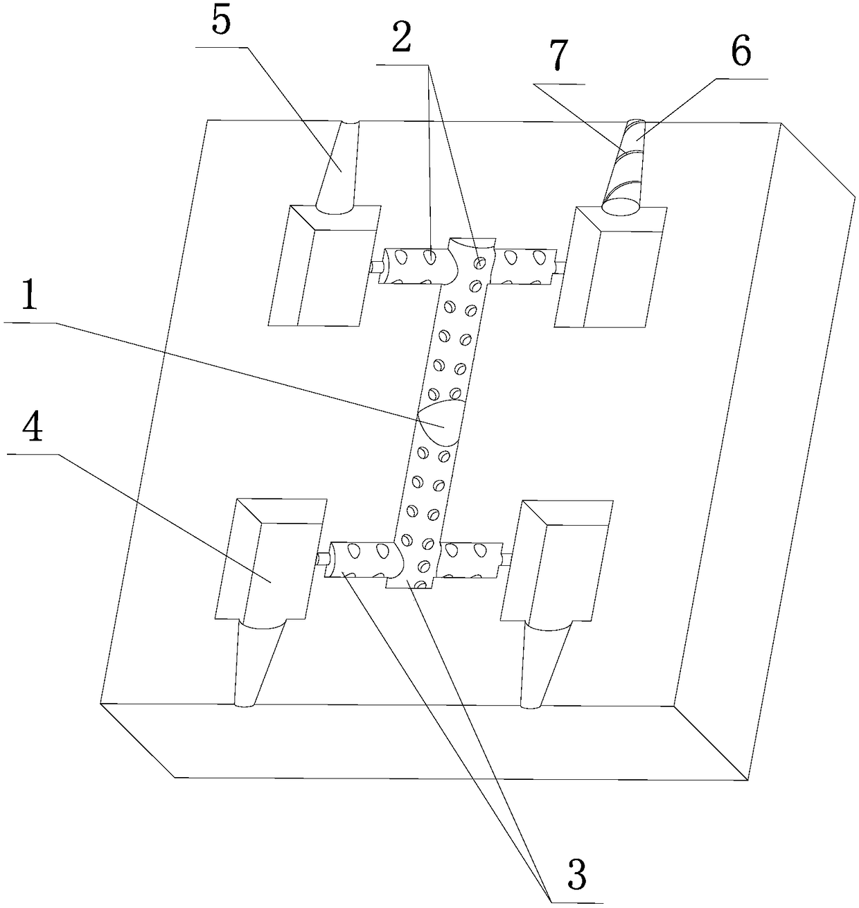
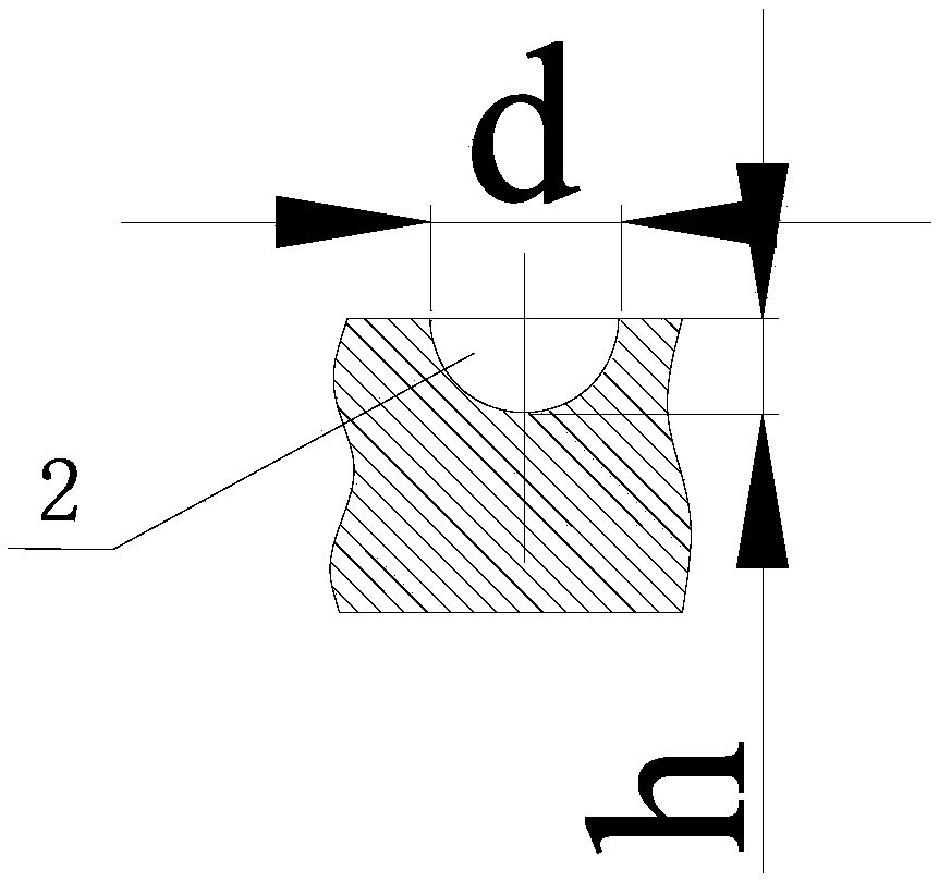
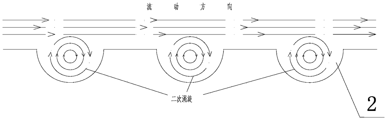
[0016] like figure 1 , figure 2 , image 3 As shown, the injection mold of the present invention is assembled by two sub-moulds. The interior of the mold is provided with a main runner 1, a sub-runner 3 and a cavity 4 which are connected in sequence. The runner walls of the main runner 1 and the sub-runner 3 are evenly distributed with a plurality of circular pits 2 .

[0017] Each sub-mold of the mold is provided with a plurality of arc-shaped grooves 5 corresponding to the cavity 4, and the two arc-shaped grooves 5 at the corresponding positions of the two sub-molds are combined to form a complete gradually decreasing radius from the inside to the outside. Round holes, each tapered round hole is tightly fitted with a circular frustum 6 whose shape matches the tapered circular hole, and the side of the circular frustum 6 is provided with ...


PUM


Abstract

The invention discloses an injection mold. The injection mold is formed by splicing two secondary molds; a main sprue (1), secondary sprues (3) and cavities (4) which successively communicate with one another are arranged inside the mold, and a plurality of circular pits (2) are uniformly distributed in sprue walls of the main sprue (1) and the secondary sprues (3); and a plurality of arc-shaped grooves (5) which are in one-to-one correspondence to the cavities (4) are formed in each secondary mold of the mold; each complete gradually reduced round hole of which the radius is gradually reduced from inside to outside is formed by combining the corresponding two arc-shaped grooves (5) at corresponding positions of the two secondary molds; a circular truncated cone (6) of which the shape is matched with that of each gradually reduced round hole is in close fit with the inside of the gradually reduced round hole; and each spiral pressure relieving groove (7) through which the corresponding cavity (4) communicates with air of the outside is formed in a side surface of the corresponding circular truncated cone (6). By the injection mold, flow resistance of melt can be reduced effectively, and pressure loss is reduced.

Description

technical field [0001] The invention relates to the field of injection molding equipment, in particular to an injection mold. Background technique [0002] Injection molding is widely used in the production and manufacture of plastic products due to its advantages of high efficiency and high quality. Injection molds are generally composed of two sub-moulds, and the interior of the mold is provided with a main runner, a sub-runner, a cavity and a pressure relief hole that are connected in sequence. During the injection molding of the injection molding machine, the melt is pumped by the barrel and flows through the nozzle, main runner, and sub-runner to the cavity. Constant friction, large flow resistance, and large pressure loss lead to insufficient filling of the melt and defects in the formed product. Moreover, in recent years, micro-injection molding technology has become more and more widely used, and the resistance of melt filling in micro-injection molding is greater....

Claims


Application Information

Patent Timeline
Patent Type & Authority Patents(China)
IPC IPC(8): B29C45/27B29C45/34
CPCB29C45/2701B29C45/34
Inventor 许少锋楼应侯何平王向佯刘毅
Owner NINGBO INST OF TECH ZHEJIANG UNIV ZHEJIANG
Why Eureka
Try Eureka