Method for testing output locking or no-output fault of digital circuit

A digital circuit and testing method technology, applied in the direction of digital circuit testing, electronic circuit testing, measuring electricity, etc., can solve the problems of signal line damage, increased difficulty, unsound working environment, etc., and achieve accuracy and reliability improvement, connection Easy to enter the form, easy to test the effect

Active Publication Date: 2017-02-08
10TH RES INST OF CETC
View PDF5 Cites 4 Cited by
  • Summary
  • Abstract
  • Description
  • Claims
  • Application Information

AI Technical Summary

Problems solved by technology

Due to the continuous use of electronic components, it will lead to aging and parameter performance degradation, and some of them change the parameter performance when the temperature changes
[0004] (2) Signal line failure
When the circuit board circuit is affected by the outside world, the signal line will be damaged and short circuit and open circuit will occur.
[0005] (3) Bad contact of circuit components
This kind of problem is the most common. If there is false welding or the solder joints are oxidized during work, it will lead to circuit board failure.
[0006] (4) Unhealthy working environment
Once the working environment does not meet the requirements of the equipment, such as humidity, temperature and electromagnetic environment, etc., the normal operation of the equipment cannot be realized
[0007] (5) Exceeded the period of use
[0012] The above four methods are conventional methods commonly used in the detection of digital circuit faults, but these method...

Method used


Image

  • Method for testing output locking or no-output fault of digital circuit
  • Method for testing output locking or no-output fault of digital circuit
  • Method for testing output locking or no-output fault of digital circuit

Examples


Embodiment Construction

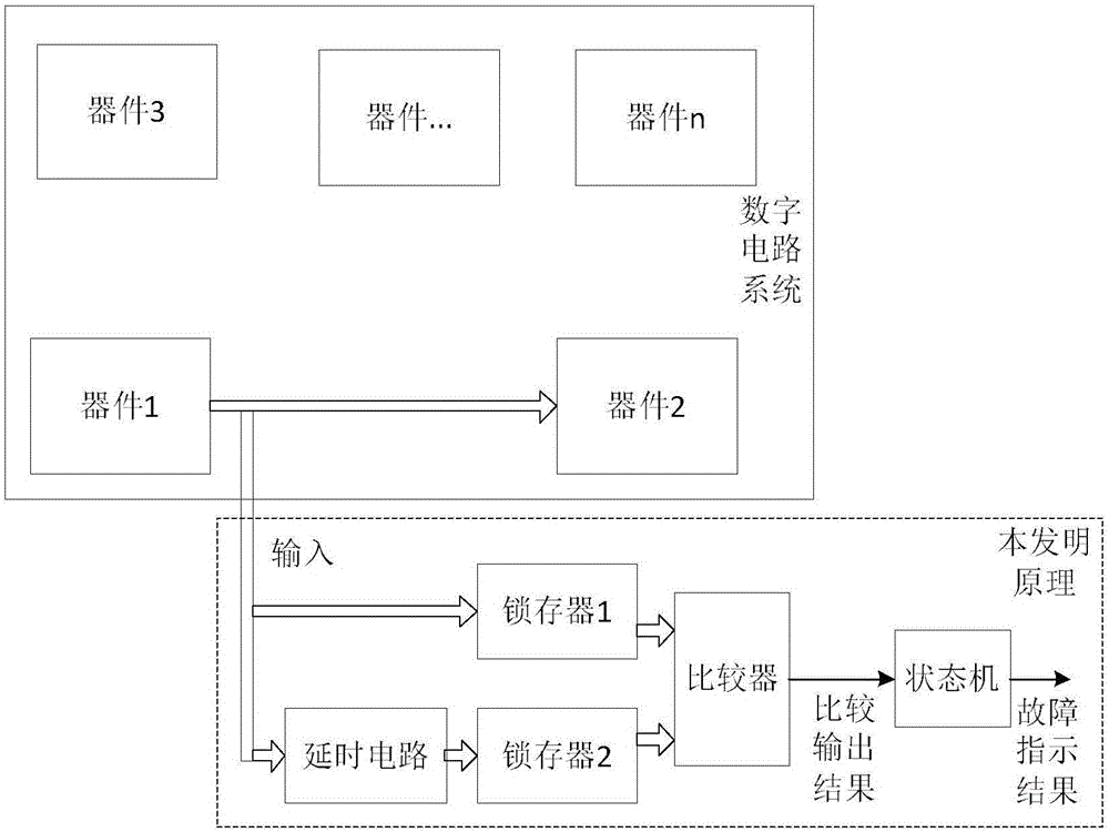
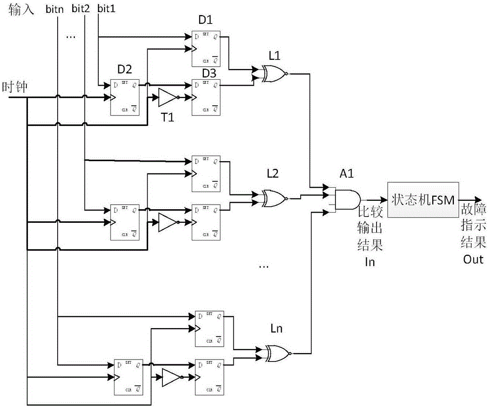
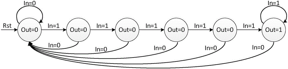
[0027] refer to figure 1 . According to the present invention, a delayer, two latches, a NOR comparator and a state machine are used to form a digital circuit fault diagnosis system, and the two input terminals of the NOR comparator are electrically connected to the latches respectively 1 output terminal and the latch 2 output terminal connected in series through the delayer; during the test, the NOR comparator is first formed by connecting the latch 2 in series with the delay circuit to the data signal output from the device on the digital circuit system at the current moment Delay and latch circuit, the current input data is delayed for a moment and then sent to latch 2 for latching; the same OR comparator will latch the data at the previous moment of latch 2 and the current output of latch 1 The data is latched at all times for NOR operation comparison. The comparison output results are counted by the state machine judgment circuit to judge whether the comparison results a...


PUM


Abstract

The invention provides a method for testing a stuck-at fault or an open-circuit fault of a digital circuit. Output faults of the digital circuit can be diagnosed online according to the method, and the false alarm rate of a system is reduced. The method is implemented according to the following technical scheme: a latch 1 and a latch serially connected through a time delay device are electrically connected to two input ends of an XNOR comparator respectively; as for data signals outputted by a device of a digital circuit system at the current moment, the XNOR comparator firstly delays the inputted current data for a moment through a time delay and latch circuit formed by the latch 2 serially connected through a time delay circuit and then sends the delayed data to the latch 2 so as to be latched; and the XNOR comparator performs XNOR operation and comparison on latch data of the latch 2 at the previous moment and latch data of the latch 1 at the current output moment, and judging whether results of continuous and repeated comparisons are consistent or not, wherein if the results are not consistent, it is shown that circuit output is normal, if the results are consistent, it is shown that a stuck-at fault or an open-circuit fault occurs in output of the digital circuit. The method provided by the invention realizes online test and diagnosis for system faults of the digital circuit.

Description

technical field [0001] The invention belongs to the field of digital circuit fault testing, and more specifically relates to a testing method for a digital circuit output locked or no output fault mode. Background technique [0002] With the rapid development of digital circuits, the functions of digital circuits are becoming more and more complex, their performance is rapidly improving, and their applications are becoming more and more extensive. Digital circuits have become the core part of more and more electronic systems, and the failure of digital circuits will greatly affect the work of the system and become the main factor for the failure of the entire circuit. There are many kinds of digital circuits, the structure and function are becoming more and more complex, the scale and complexity of the circuit system are rising sharply, and the corresponding circuit maintenance work is also facing new difficulties. Digital circuit failure is caused by poor contact, damage t...

Claims


Application Information

Patent Timeline
IPC IPC(8): G01R31/317
CPCG01R31/31712
Inventor 陈文豪赖作镁
Owner 10TH RES INST OF CETC
Why Eureka
Try Eureka