Wind tunnel operation fault diagnosis system based on distributed architecture

A distributed architecture and fault diagnosis technology, applied in the testing, measuring devices, instruments, etc. of machine/structural components, which can solve the problems of the gas main heater being easily burnt out in an instant, the equipment layout being scattered, and the loss etc.

Active Publication Date: 2018-10-02
BEIJING AEROSPACE INST OF THE LONG MARCH VEHICLE +1
View PDF4 Cites 12 Cited by
  • Summary
  • Abstract
  • Description
  • Claims
  • Application Information

AI Technical Summary

Problems solved by technology

The structure of the gas flow wind tunnel system is as follows: figure 1 As shown, the functions are huge and complex, the equipment layout is relatively scattered, there are many control nodes and collection nodes, and the requirements for the supply parameters

Method used


Image

  • Wind tunnel operation fault diagnosis system based on distributed architecture
  • Wind tunnel operation fault diagnosis system based on distributed architecture
  • Wind tunnel operation fault diagnosis system based on distributed architecture

Examples


Embodiment 1

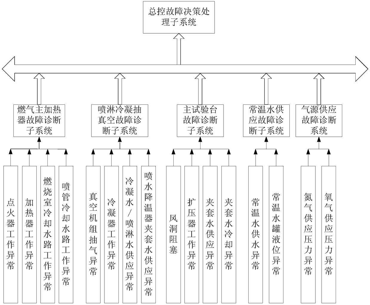
[0097] Example 1: The abnormal operation of the main gas heater triggers the shutdown of the wind tunnel

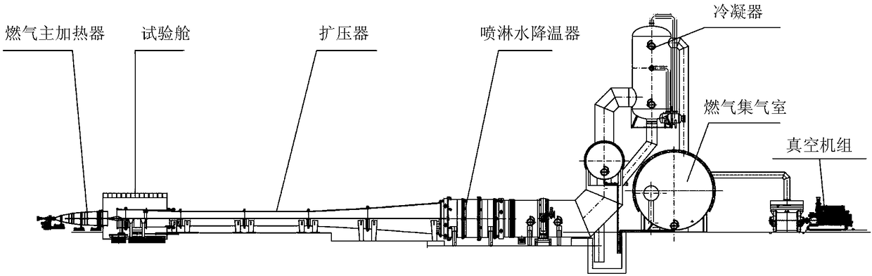
[0098] As the source of high-temperature gas production, the gas main heater plays a vital role. This embodiment adopts a two-stage ignition method in which the torch igniter ignites the heater. Press high-pressure, small-flow gas, oxygen, and kerosene into the igniter for mixed combustion according to a certain ratio and action sequence. After the ignition is stable, the condition 0.8×P is met. 点火器额定 ≤P 点火器 ≤1.2×P 点火器额定 At this time, a large flow of gas, oxygen and kerosene are pressed in from the oxygen inlet and oil inlet of the heater respectively under high pressure, fully mixed and combusted in the combustion chamber, and a high-temperature supersonic gas flow field is generated through the aerodynamic action of the nozzle, and then the condition 0.8 is satisfied. ×P 加热器额定 ≤P 加热器 ≤1.2×P 加热器额定 , 0.8×P 燃烧室水额定 ≤P 燃烧室水 ≤1.2×P 燃烧室水额定 , 0.8×P 喷管水额定 ≤P 喷管水 ≤1.2×P...

Embodiment 2

[0100] Example 2: An abnormality in the jacket cooling water supply of the main test bench triggers an alarm and shutdown of the wind tunnel

[0101] The main test bench consists of two parts: the test cabin and the diffuser. After the heat-proof structure test piece has undergone thermal assessment in the test cabin, the high-temperature gas is discharged to the rear-end spray condensation vacuum equipment through the deceleration and pressurization of the diffuser. Therefore, the water cooling and heat protection requirements of the main test bench are very high, and sufficient cooling water supply must be ensured, otherwise the equipment may be damaged. Satisfy P during the test 试验舱 试验舱高限 ,P 试验舱 ≤P 扩压器 , F 夹套水二级低限 夹套水 夹套水二级高限 , T 夹套出水 夹套出水高限 Continue the test until the set test time is reached, otherwise, a secondary fault alarm signal will be sent to the general control fault decision-making processing subsystem, and if it is more serious, it will directly trigger the ...


PUM


Abstract

The invention relates to a wind tunnel operation fault diagnosis system based on a distributed architecture. The wind tunnel operation fault diagnosis system belongs to the technical field of aerospace ground thermal protection and insulation tests, and is used for performing real-time monitoring and state judgment on an operating state of a combustion gas flow supersonic wind tunnel test system,triggering a general control fault decision-making processing subsystem to alarm or coordinate subsystems to shut down by steps according to a set fault processing strategy when the subsystems judge that an abnormal situation occurs, effectively ensuring safety of processing equipment in the field, and guaranteeing reliable operation of the test. The wind tunnel operation fault diagnosis system provides a technical guarantee for the state monitoring and fault diagnosis of wind tunnel equipment, provides software and hardware support for stable operation of the wind tunnel system, can respond to the fault timely since a fault response speed reaches ms level, and greatly improves the efficiency and reliability of fault diagnosis.

Description

technical field [0001] The invention relates to a wind tunnel operation fault diagnosis system based on a distributed architecture, which is used for real-time monitoring and emergency treatment of the operation status of the gas flow supersonic wind tunnel test system, to ensure the reliable operation of the test equipment, and belongs to the aerospace ground heat insulation field of test technology. Background technique [0002] Ground test assessment is an important link in the development of warhead heat protection system. Due to its high power and high total temperature, the gas flow wind tunnel is one of the irreplaceable means for the thermal structure test and assessment of the heat protection system. The high-temperature gas flow supersonic wind tunnel mainly uses the main gas heater to generate high-temperature supersonic gas flow, and conducts partial or comprehensive thermal assessment of the heat-resistant structure specimens in the test chamber. After the asse...

Claims


Application Information

Patent Timeline
IPC IPC(8): G01M9/04G01M9/06
CPCG01M9/04G01M9/06
Inventor 张凯齐斌田宁邹样辉曹知红李彦良张利嵩那伟杨驰赵玲夏吝时岳晖宋文潇姜一通李文浩张昕曹宇清鲁宇朱广生李建林孟刚周岩水涌涛张岩陈卫国黄凯王树信
Owner BEIJING AEROSPACE INST OF THE LONG MARCH VEHICLE
Why Eureka
Try Eureka