
Distributed photovoltaic interactive terminal and method

A distributed photovoltaic and interactive terminal technology, applied in photovoltaic power generation, AC network circuits, electrical components, etc., can solve problems such as power outages in the entire network, high-cost generating units, and impact on the power grid

Active Publication Date: 2017-02-08
CHINA ELECTRIC POWER RES INST +3
View PDF3 Cites 2 Cited by
  • Summary
  • Abstract
  • Description
  • Claims
  • Application Information

AI Technical Summary

Problems solved by technology

However, due to its inherent weaknesses, the cascading power supply system can no longer meet the load's increasingly higher requirements for power supply quality and reliability.
From a security point of view, any disturbance caused by a fault in a large power grid will affect the entire power grid, and may even cause a large-scale power outage or even a collapse of the entire network
From an economic point of view, the centralized power supply system needs to build a large number of expensive generator sets in order to adjust the short-term peak power supply, which is economically unreasonable.

Method used


Image

  • Distributed photovoltaic interactive terminal and method
  • Distributed photovoltaic interactive terminal and method
  • Distributed photovoltaic interactive terminal and method

Examples


Embodiment Construction

[0042] In order to make the object, technical solution and advantages of the present invention more clear, the present invention will be further described in detail below in conjunction with the examples. It should be understood that the specific embodiments described here are only used to explain the present invention, not to limit the present invention.

[0043] The application principle of the present invention will be described in detail below in conjunction with the accompanying drawings.

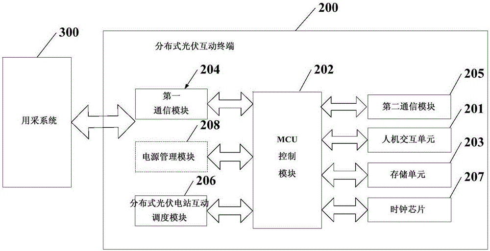
[0044] Such as figure 1 As shown, a distributed photovoltaic interactive terminal 200 includes a communication unit, a human-computer interaction unit 201, a storage unit 203 and a main control unit; the communication unit, the human-computer interaction unit 201 and the storage unit 203 are respectively connected to the main control unit ;

[0045] The communication unit is used to collect the power consumption information of the distributed photovoltaic power station in the mining ...


PUM


Abstract

The invention discloses a distributed photovoltaic interactive terminal and method. The distributed photovoltaic interactive terminal comprises a master control unit and also comprises a communication unit, a human-computer interaction unit and a storage unit connected to the master control unit. The communication unit is used for collecting the electricity use information of a distributed photovoltaic power station and the interaction intention of the distributed photovoltaic power station and sending the electricity use information and the interaction intention to a dispatching center and also is used for receiving the interaction time period, the interaction amount Cset and the electricity price in interaction issued by a master station server. The human-computer interaction unit is used for displaying the interaction time period, the interaction amount Cset, the electricity price in interaction and the electricity use information of the distributed photovoltaic power station issued by the master station server of the dispatching center. The master control unit is used for calculation the interaction amount into which the distributed photovoltaic power station can participate according to the interaction time period and the interaction amount Cset. The storage unit is used for storing the data information generated in the interaction process. According to the distributed photovoltaic interactive terminal and method, the two-way communication requirement of the distributed photovoltaic power station and the master station server can be satisfied, and the distributed photovoltaic interactive terminal and the method can be used for realizing the interaction based on the time-sharing electricity price and the subsidy incentive between a distribution network and the distributed photovoltaic power station.

Description

technical field [0001] The present invention relates to an interactive terminal and method, in particular to a distributed photovoltaic interactive terminal and method. Background technique [0002] In the process of economic development, along with energy consumption, the resource demand structure dominated by fossil energy will damage the earth's environment, that is, the 3E problem. The way to solve the 3E problem is to rely on the development of clean energy technology to realize energy, A virtuous circle of environment and economy. Compared with fossil fuels such as coal, oil, and natural gas, solar energy is an ideal renewable green energy due to its huge energy storage capacity, ubiquity, and economy. [0003] Photovoltaic power generation systems usually include solar cell components, batteries, and charge and discharge controllers. If there is an AC load or connected to the grid, different inverters need to be configured. Photovoltaic cells convert solar energy d...

Claims


Application Information

Patent Timeline
IPC IPC(8): H02J3/38H02J13/00
CPCH02J3/383H02J13/0075Y04S10/123Y02E10/56Y02E40/70Y04S40/126Y02E60/00
Inventor 王国功江兵崔云跃汪春齐蓬勃夏俊荣徐红斌徐军张祥文戈富国刘海璇张永勤周昶王鹏
Owner CHINA ELECTRIC POWER RES INST
Learn More