Cerenkov radiation imaging method and system

A radiation imaging and irradiation technology, applied in medical science, sensors, diagnostic recording/measurement, etc., can solve the problems of long imaging time, low detection efficiency, high cost, etc., to reduce background noise, improve imaging signal-to-noise ratio, Effect of high image signal-to-noise ratio

Pending Publication Date: 2017-02-15
NANJING RAYCAN INFORMATION TECH
View PDF11 Cites 5 Cited by
  • Summary
  • Abstract
  • Description
  • Claims
  • Application Information

AI Technical Summary

Problems solved by technology

A high-density scintillator is required to convert high-energy photons into visible light photons, so it has a high cost
[0004] However, due to the lens design of the exi

Method used


Image

  • Cerenkov radiation imaging method and system
  • Cerenkov radiation imaging method and system
  • Cerenkov radiation imaging method and system

Examples


example 1

[0065] The parameters of data processing in this embodiment are listed here:

[0066] The actual system used in step (1) uses a dark box with a size of 1.7m×1.6m×1.7m. The radiation source is an electron beam, and after the electron beam is irradiated to the organism, the Cerenkov radiation effect can occur;

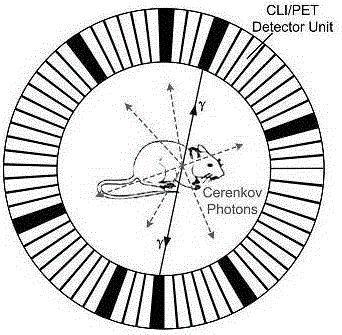
[0067] Step (2) Use a silicon photomultiplier tube with red light enhancement, and the detector adopts a fully enclosed spherical shell structure;

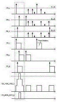
[0068] The matching time of step (3) is about 7 ns, and the matching judgment adopts offline time matching processing;

[0069] Step (4) Using the Monte Carlo modeling method to obtain the probability density function of each detection hole;

[0070] Step (5) uses the analytical nuclide distribution reconstruction method to directly plot the time and position of Cherenkov.

example 2

[0072] The parameters for processing data in this application example 2 are listed here:

[0073] The actual system used in step (1) uses a dark box with a size of 1.7m×1.8m×1.8m. The radiation source is 124I-NaI of 511kev;

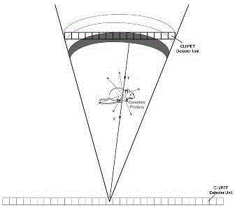
[0074] Step (2) adopts all-digital photomultiplier tubes, and the detector adopts a flat structure;

[0075] Step (3) The coincidence time is about 10 ns, and the coincidence judgment adopts the online time coincidence processing;

[0076] Step (4) Using the experimental data fitting method to obtain the probability density function of each detection hole;

[0077] In step (5), the iterative nuclide distribution reconstruction method is used to approximate the time and position of Cherenkov, and the termination criterion of the iteration is that the average jitter of the image is less than 1000 counts.

[0078] The method and system of the present invention can be used in nuclear techniques that radiate charged particles, including nuclear detection, n...


PUM


Abstract

The invention provides a cerenkov radiation imaging method. The cerenkov radiation imaging method comprises the following steps: injecting isotopes capable of emitting charged particles; reading the count of cerenkov photons emitted by the charged particles and transmitted to a detector module and the time for each photon count; carrying out time coincidence on the read cerenkov photons; estimating the occurring position of the cerenkov event according to the relative location of the photons in holes; and carrying out judgment and selection according to the energy and angle widening of the plurality of photons, and after triggering, acquiring other interesting information such as angle and momentum from the electric pulse set of the cerenkov event. The invention further provides a cerenkov radiation imaging system. The cerenkov radiation imaging system comprises an isotope injection module, a photoelectric detector module, a multi-case time coincidence module, a cerenkov event estimation module and a nuclide distribution image reconstruction module. With the adoption of the cerenkov radiation imaging method and the cerenkov radiation imaging system provided by the invention, the spatial resolution and imaging signal-to-noise ratio of the system can be effectively improved, and the cerenkov radiation imaging method is particularly suitable for being applied in in-vivo small animal imaging and superficial clinical diagnosis.

Description

technical field [0001] The invention relates to the fields of digital signal processing, photoelectric signal processing and nuclear detection, in particular to a single-photon time-resolved Cerenkov radiation imaging method and system. Background technique [0002] Cerenkov radiation detection is an optical imaging method that emits photons of visible and near-infrared light by the Cherenkov effect. Radioactive isotopes with Cerenkov radiation can be used as probes for in vivo imaging. By participating in various physiological and biochemical processes of organisms, they can constitute a new imaging method. In optical imaging and multimodal medical imaging It has wide application value. In 2010, Alessandro Ruggiero et al. (J. Nucl. Med.2010,51:1123-1130) in the United States confirmed that high-speed charged particles emitted by radioactive isotopes with α or β decay can emit Cerenkov in the medium by using a single-view lens. radiation, and the radiated photons have a ce...

Claims


Application Information

Patent Timeline
IPC IPC(8): A61B5/00
Inventor 谢庆国邓贞宙
Owner NANJING RAYCAN INFORMATION TECH
Why Eureka
Try Eureka