Positron emission cerenkov-gamma bi-radiation imaging method and device

A technology of positron emission and imaging method, which is applied in computerized tomography scanner, echo tomography, etc., can solve the problem of data loss, achieve the effects of rejecting interference, high system accuracy, and improving imaging signal-to-noise ratio

Pending Publication Date: 2017-02-15
NANJING RAYCAN INFORMATION TECH
View PDF7 Cites 4 Cited by
  • Summary
  • Abstract
  • Description
  • Claims
  • Application Information

AI Technical Summary

Problems solved by technology

Conventional PET loses part of the available data because it only detects gamma photons annihilated by positrons

Method used

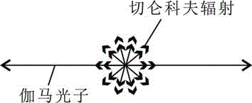
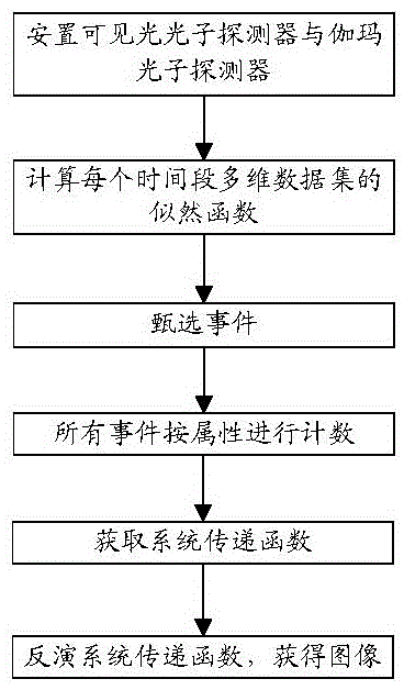
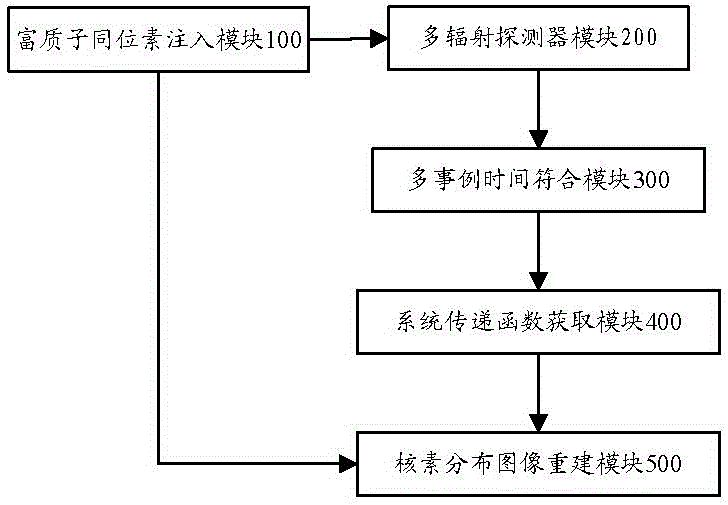

Image

  • Positron emission cerenkov-gamma bi-radiation imaging method and device
  • Positron emission cerenkov-gamma bi-radiation imaging method and device
  • Positron emission cerenkov-gamma bi-radiation imaging method and device

Examples


example 1

[0065] The parameters of data processing in this embodiment are listed here:

[0066] The actual device used in step (1) is a dark box with a size of 1.5m×1.5m×1.5m. The 511keV positron annihilates the gamma photon 18F-FDG. The red-enhanced silicon photomultiplier tube is used as the photosensitive element for Cherenkov photon detection. The scintillation detector of yttrium lutetium silicate / photomultiplier tube / blue-violet silicon photomultiplier tube is used as the gamma photon detection element, and the specific composition is as follows: As shown in Figure 7, the combination of detector units adopts a ring structure;

[0067] Step (2) Use the angle (2-D), time (1-D), position (3-D), and energy (1-D) of the positron event as attribute values ​​to establish a two-particle likelihood function;

[0068] Step (3) The coincidence time is about 2ns, and the coincidence judgment adopts offline time coincidence processing, and the particle counting is gated;

[0069] Step (4) R...

example 2

[0073] The parameters for processing data in this application example 2 are listed here:

[0074] The actual device used in step (1) is a dark box with a size of 0.15m×0.15m×0.15m. The 511keV positron annihilates the gamma photon 18F-FDG. The red-enhanced silicon photomultiplier tube is used as the photosensitive element for Cherenkov photon detection. The scintillation detector of lanthanum bromide / blue-violet silicon photomultiplier tube is used as the gamma photon detection element, and the combination of the detector unit adopts 12 flat plates structure;

[0075] Step (2) Use the angle (2-D), time (1-D), position (3-D), and energy (1-D) of the positron event as attribute values ​​to establish a two-particle likelihood function;

[0076] Step (3) The coincidence time is about 2ns, and the coincidence judgment adopts offline time coincidence processing, and the particle counting is gated;

[0077] Step (4) adopts the method of list data, without rearranging the projection...


PUM


Abstract

The invention provides a positron emission cerenkov-gamma bi-radiation imaging method. The positron emission cerenkov-gamma bi-radiation imaging method comprises the following steps: placing a visible light photon detector and a gamma photon detector, and acquiring a pulse data set; calculating a joint likelihood probability function of a multi-dimensional data sample during each time period; judging that whether the currently received data slot comes from a positron emission event or not; accumulating all the positron emission events; establishing a transfer function of the system for each voxel; and inverting the input of the transfer function. The invention further provides a positron emission cerenkov-gamma bi-radiation imaging device. The positron emission cerenkov-gamma bi-radiation imaging device comprises a proton-rich isotope injection module, a multi-radiation detector module, a multi-case time coincidence module, a system transfer function acquiring module and a nuclide distribution image reconstruction module. With the adoption of the method and the device provided by the invention, the spatial resolution, device sensitivity and imaging signal-to-noise ratio of the positron imaging device can be effectively improved, and the positron emission cerenkov-gamma bi-radiation imaging method is particularly suitable for the application of the positrons in nondestructive testing and biomedical imaging.

Description

technical field [0001] The invention relates to the fields of digital signal processing, photoelectric signal processing and nuclear detection, in particular to an imaging method and device for single-photon time-resolved positron emission Cerenkov-Gamma dual radiation. Background technique [0002] Positron Emission Tomography (PET) is a non-invasive imaging method that can noninvasively, quantitatively and dynamically evaluate the metabolic level, biochemical reactions, functional activities and perfusion of various organs in the human body. As a highly sensitive functional imaging device, PET has unique value in early diagnosis, treatment planning, efficacy monitoring and evaluation of tumors, cardiovascular system diseases and nervous system diseases. [0003] With the continuous deepening of the application of PET instruments in clinical diagnosis and treatment, the medical community has put forward new requirements for the performance and functions of PET instruments, ...

Claims


Application Information

Patent Timeline
Patent Type & Authority Applications(China)
IPC IPC(8): A61B6/03
Inventor 邓贞宙谢庆国
Owner NANJING RAYCAN INFORMATION TECH
Why Eureka
Try Eureka