
A kind of micro reaction unit and micro reactor

A technology of micro-reactions and reactants, applied in chemical/physical/physical chemical reactors, chemical instruments and methods, chemical/physical/physical chemical processes, etc., can solve the problem of small processing capacity, large pressure loss, and non-reaction channel parts Many problems, to achieve the effect of reducing the pressure drop of the reaction and enhancing the heat transfer of the fluid

Active Publication Date: 2020-04-14
SHANDONG HIMILE CHEM TECH
View PDF6 Cites 0 Cited by
  • Summary
  • Abstract
  • Description
  • Claims
  • Application Information

AI Technical Summary

Problems solved by technology

[0015] 1. There are many non-reaction channels on the microreactor, the effective utilization rate of a single reaction piece is low, the distance of the micro-reverse channel on the reaction piece is short, the liquid holding capacity of the channel is small, and the processing capacity is small;
[0016] 2. Each adjacent channel needs to complete a 180° turn, resulting in large pressure loss and high energy consumption;
[0017] 3. The heat exchange channel and the reaction channel are separated by at least one sheet thickness, and the heat exchange efficiency is low;
[0018] 4. There are many non-reaction channels on the microreactor, the effective utilization rate of a single reaction piece is low, the distance of the micro-reverse channel on the reaction piece is short, the number of pieces required to complete a certain mixing and / or reaction is large, and the cost is high

Method used


Image

  • A kind of micro reaction unit and micro reactor
  • A kind of micro reaction unit and micro reactor
  • A kind of micro reaction unit and micro reactor

Examples


Embodiment 1

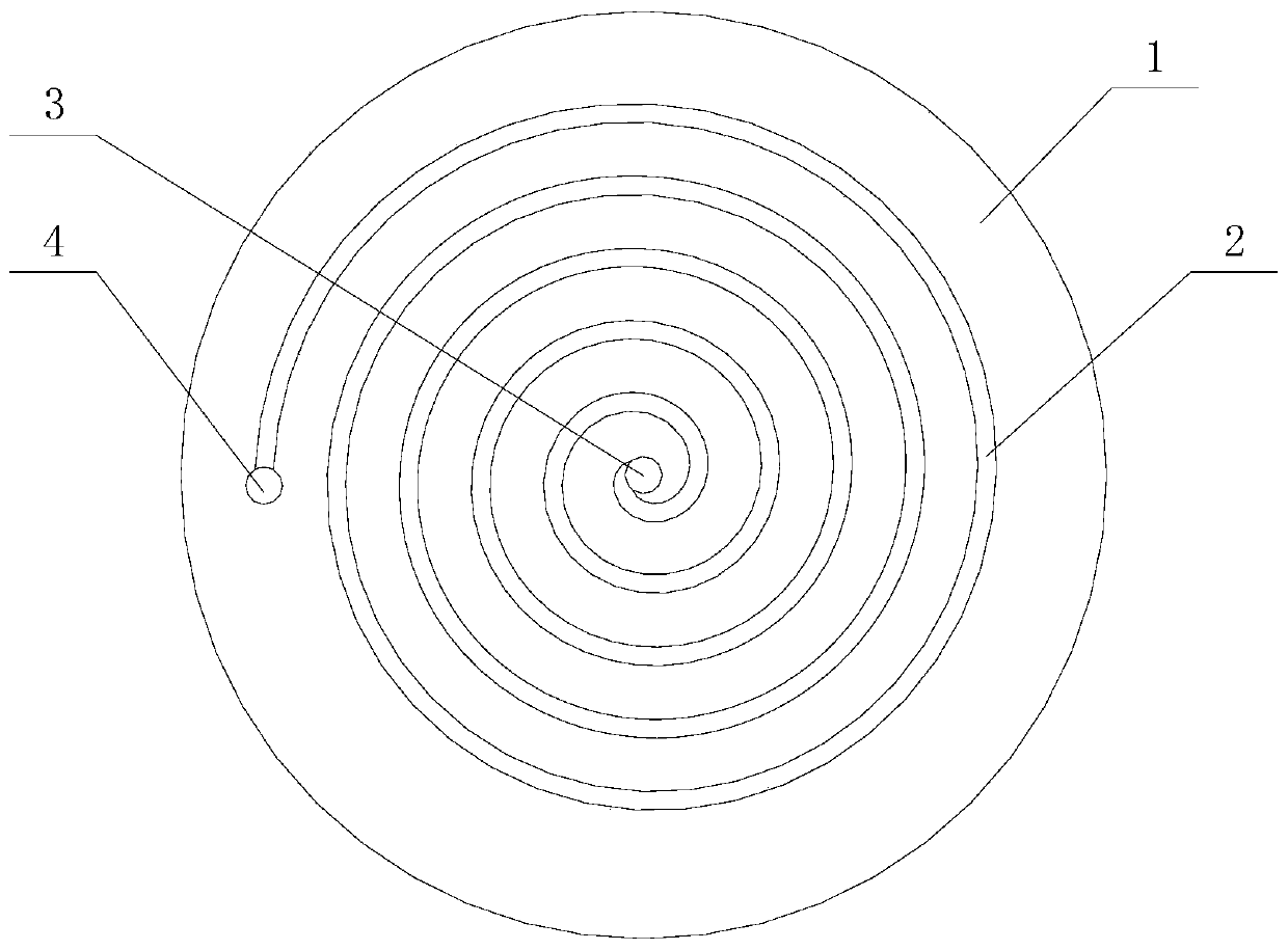
[0051] Such as figure 1As shown, the embodiment of the present invention provides a micro-reaction unit, including a body 1, the body 1 is a plate structure, the body 1 is provided with a reactant inlet 3 and a reactant outlet 4, a reactant inlet 3 and a reactant outlet 4 are connected through the reaction channel 2, and the reaction channel 2 is spirally coiled around the reactant inlet 3. Alternatively, the reaction channel 2 can also be spirally wound around the reactant outlet 4 .

[0052] In this embodiment, the structure of the reaction channel of the microreactor is improved, and a helical reaction channel structure is adopted to make the micro-reaction fluid form a helical shape, which is beneficial to the sufficient mixing of the reaction fluid.

[0053] Preferably, the body 1 of the plate-like structure includes opposite first and second end faces, and the reactant inlet 3 or the reactant outlet 4 has a centerline, and on the first end face or the second At least o...

Embodiment 2

[0056] Preferably, it further includes a sealing plate 12 connected to the end surface of the body 1 having the first spiral groove. The first spiral groove on the body 1 is covered by the sealing plate 12 to form the reaction channel 2 . Such a structural design makes the end surface of the main body 1 and the sealing plate 12 bonded and connected.

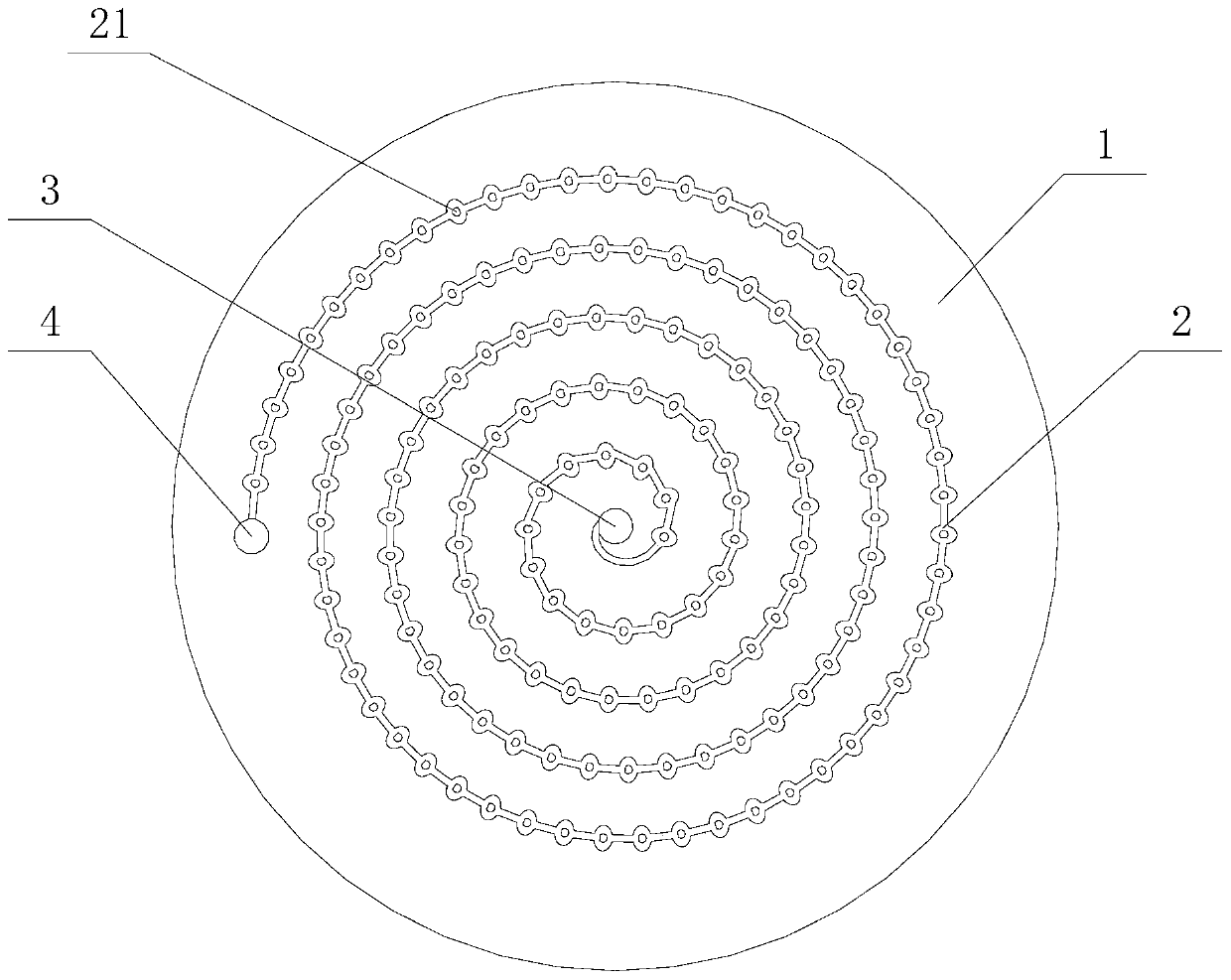
[0057] Preferably, any position on the reaction channel is also provided with a spoiler structure 21 for disturbing the fluid flowing through the position; the spoiler structure 21 has a spoiler effect on the fluid passing through, so The fluids are mixed, causing the fluids to react.

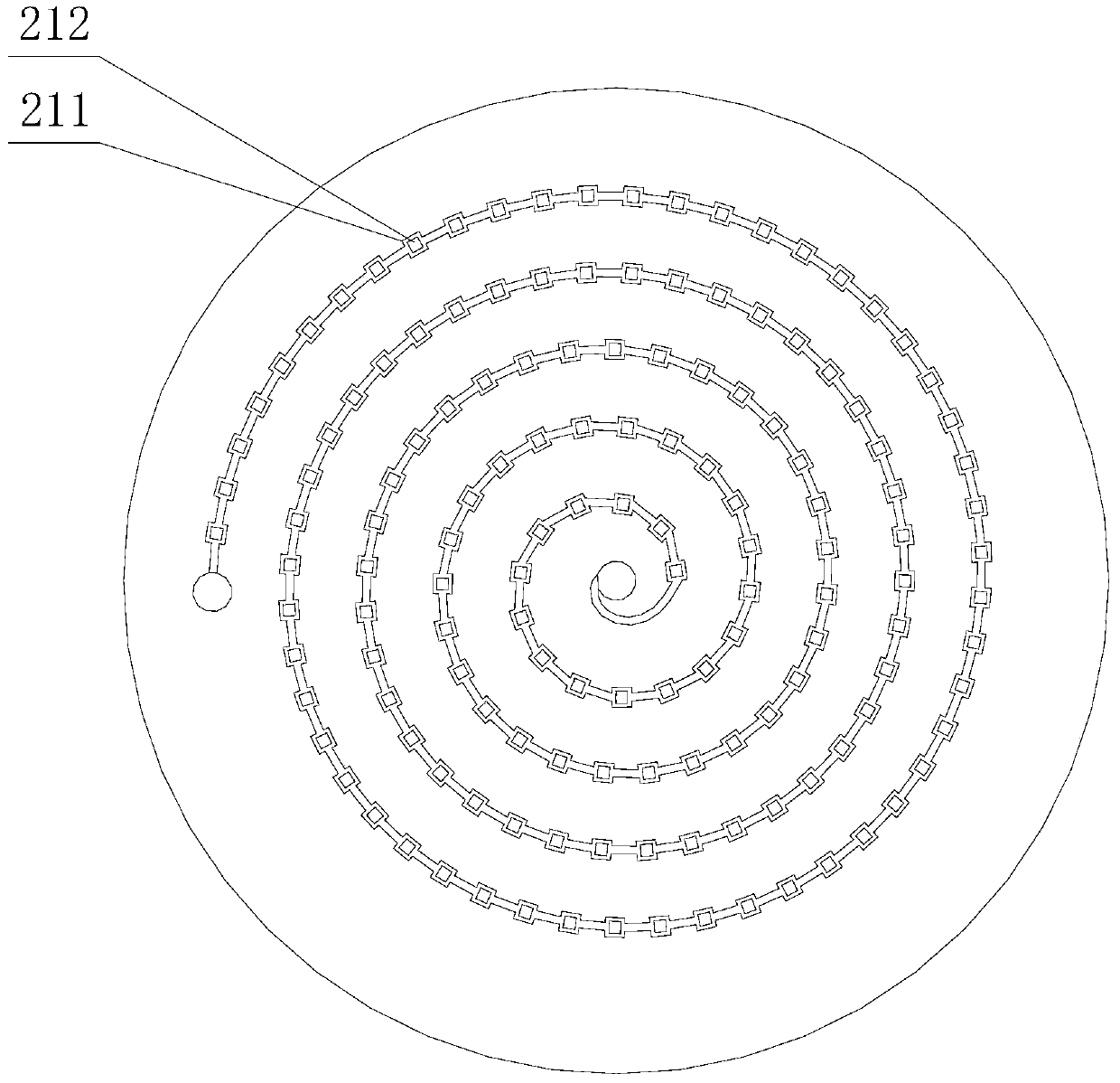
[0058] Further preferably, the flow turbulence structure 21 includes a blocking structure 212 arranged at any position in the reaction channel to block the flow of the reaction fluid, or the flow turbulence structure 21 is included at any position in the reaction channel An expansion structure 211 formed by expanding the channel;

[0059] Furth...


PUM


Abstract

The invention discloses a micro-reaction unit. The micro-reaction unit comprises a body with a plate-like structure, wherein a reactant inlet and a reactant outlet are formed in the body and communicate through a reaction channel, and the reaction channel surrounds the reactant inlet or the reactant outlet spirally. On the basis, by means of a heat exchange channel with a spiral structure, heat exchange of a fluid is enhanced, and the controllability of micro-reaction heat exchange is improved. The micro-reaction unit has another advantage that multiple stages of micro-reactors can be combined and used conveniently and can be combined freely as required and applied flexibly to form a micro-reaction system.

Description

technical field [0001] The invention relates to the technical field of reaction equipment, in particular to a microreactor used in the chemical industry, medicine and other fields, so that the reaction medium can be fully mixed in the reaction channel of the microreactor and perform physical or chemical reactions. Background technique [0002] A microreactor is a microreactor with a characteristic size between 10 and 3000 μm manufactured by precision machining technology. The reaction medium can be gaseous, liquid or dispersed, used for physical reactions of reactants in the channel, such as mixing, dispersion, emulsification, suspension, etc.; or chemical reactions, such as oxidation, reduction, substitution, elimination, addition , ligand exchange, and ion exchange, or more specifically, polymerization, alkylation, dealkylation, nitration, peroxidation, sulfoxidation, epoxidation, ammoxidation, hydrogenation, dehydrogenation, organometallic reactions, Noble metal reaction...

Claims


Application Information

Patent Timeline
Patent Type & Authority Patents(China)
IPC IPC(8): B01J19/00
CPCB01J19/0093B01J2219/00786B01J2219/00851B01J2219/00873B01J2219/00889
Inventor 李凤李处来杨志华任苗苗黄振李鹏飞
Owner SHANDONG HIMILE CHEM TECH
Learn More