Molten glass heating device, glass manufacturing device and method for manufacturing glass articles
A technology for melting glass and heating devices, applied in glass manufacturing equipment, manufacturing tools, glass production, etc., can solve problems such as insufficient heating of branch pipes, and achieve the effect of suppressing inhomogeneity
- Summary
- Abstract
- Description
- Claims
- Application Information
AI Technical Summary
Problems solved by technology
Method used
Image


Examples
no. 1 Embodiment approach >
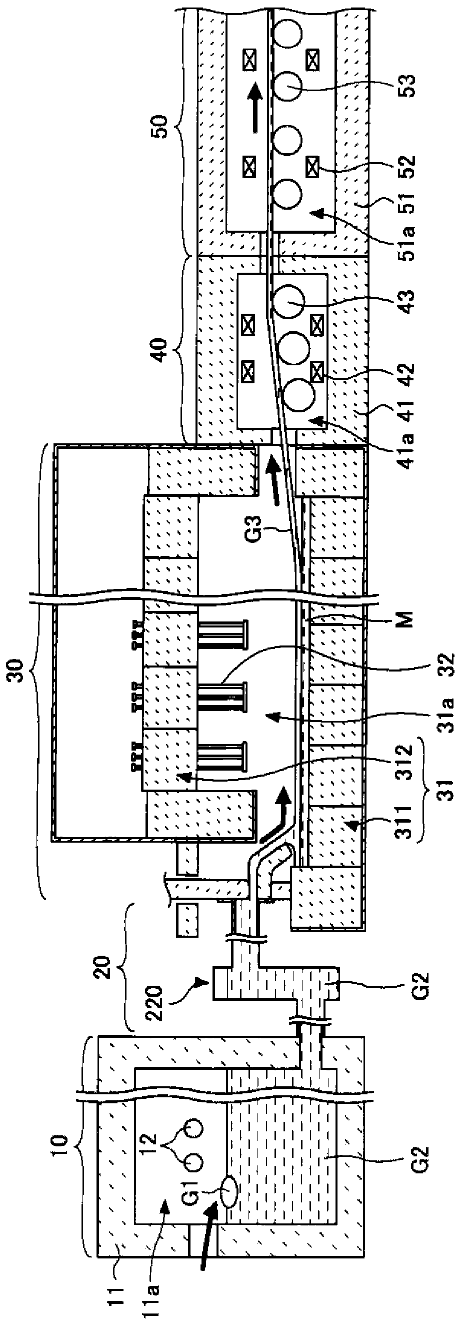
[0094] Next, refer to image 3 , the molten glass heating device 210 of the present invention will be described. image 3 It is a schematic diagram explaining the molten-glass heating apparatus 210 which concerns on 1st Embodiment of this invention.
[0095] The molten glass heating device 210 has a composite pipe structure 220 and an electric heating unit 230 . The composite pipe structure 220 includes a conduit forming a flow path through which the molten glass G2 passes. The energization heating unit 230 energizes and heats the composite pipe structure 220 .
[0096] image 3 The composite pipe structure 220 shown has a main pipe (also referred to as a main pipe) 1 as a conduit, an upper branch pipe 2 and a lower branch pipe 3 .
[0097] The main pipe 1 extends substantially vertically with respect to the horizontal direction, and the upper branch pipe 2 branches from the main pipe 1 on the upper side of the main pipe 1 and communicates with the inside of the main pipe ...
no. 2 Embodiment approach >
[0180] In this embodiment, for the figure 1 A case where two of the above-mentioned molten glass heating devices are arranged side by side in the shown molten glass conveying device 20 will be described.
[0181] Figure 5 A system 200 having a molten glass heating device according to the second embodiment of the present invention is shown.
[0182] and image 3 The composition is the same, in Figure 5 In the composite pipe structure 220 of the molten glass heating device 210 described on the left side, the lower branch pipe 3 is an introduction pipe for introducing the molten glass G2 into the inlet side of the main pipe 1, and the upper branch pipe 2 is a discharge pipe for discharging the molten glass G2 from the main pipe 1. Tube.
[0183] In the composite pipe structure 250 of the second molten glass heating device 240, the upper branch pipe 2R is an introduction pipe for introducing the molten glass G2 discharged from the upper branch pipe 2 into the inlet side of ...
Embodiment
[0189] For the above-mentioned molten glass heating device, the dimensions were changed, and the surface temperature of the composite pipe structure was calculated by simulation (finite element method). The following examples 1 to 7 are examples, and examples 8 to 10 are comparative examples.
[0190]
[0191] In Example 1, the dimensions of each part in the molten glass heating apparatus were set as follows.
[0192] Head height Hm: 1000mm
[0193] Main pipe inner diameter D1: 200mm
[0194] Branch length L: 450mm
[0195] Branch pipe inner diameter D2: 200mm
[0196] The distance h between the upper end of the main pipe and the upper end of the branch pipe: 220mm
[0197] In examples 2 to 10, the dimensions of each part in the molten glass heating device of example 1 are changed as follows Figure 6 shown.
[0198] exist Figure 6In the table, T0 represents the temperature of the central part of the main pipe 1, T1 represents the temperature of the upper part of the...
PUM
| Property | Measurement | Unit |
|---|---|---|
| height | aaaaa | aaaaa |
| length | aaaaa | aaaaa |
| height | aaaaa | aaaaa |
Abstract
Description
Claims
Application Information
 - R&D
- Intellectual Property
- Life Sciences
- Materials
- Tech Scout
- Unparalleled Data Quality
- Higher Quality Content
- 60% Fewer Hallucinations
Browse by: Latest US Patents, China's latest patents, Technical Efficacy Thesaurus, Application Domain, Technology Topic, Popular Technical Reports.
© 2025 PatSnap. All rights reserved.Legal|Privacy policy|Modern Slavery Act Transparency Statement|Sitemap|About US| Contact US: help@patsnap.com