Special travelling frame for pure electric hydraulic excavator

A hydraulic excavator and walking frame technology, applied in the field of hydraulic pressure, can solve problems such as easy breakage, achieve the effects of not being easy to twitch, simplify the disassembly process, and improve safety

Active Publication Date: 2017-02-15
LANZHOU UNIVERSITY OF TECHNOLOGY
View PDF5 Cites 0 Cited by
  • Summary
  • Abstract
  • Description
  • Claims
  • Application Information

AI Technical Summary

Problems solved by technology

[0007] Compared with the background technology, the present invention has the beneficial effects that: the main support beam 3 and the auxiliary support beam 4 of the present invention jointly support the branch line frame 8, which improves the problem that the connection between the cantilever extension device and the walking frame 1 is easily broken, and the branch line The frame connecting device 6 simplifies the disassembly and assembly process of the branch frame 8, making the replacement, transportation and maintenance of the branch frame 8 more convenient. Because of its simple structure, the end of the excavator can carry a variety of wire reels, tool boxes, etc. under the same interface. The solution becomes possible. The cable locking device 10 compresses the cable through the lead screw wrench, and locks the wrench through the latch, so that the cable is not easy to twitch during the retraction process, which improves the safety of the electric excavator, and supports the branch line frame through the hydraulic cylinder 2. 8 can provide a large supporting force, and at the same time avoid the deformation caused by excessive force in the rigid support. When the branch frame 8 is unloaded, the branch frame base 5 can be retracted by the hydraulic cylinder 2, which improves the electric excavator. mobility

Method used


Image

  • Special travelling frame for pure electric hydraulic excavator
  • Special travelling frame for pure electric hydraulic excavator
  • Special travelling frame for pure electric hydraulic excavator

Examples


Embodiment Construction

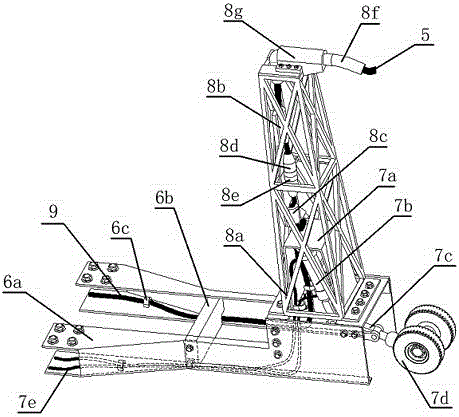
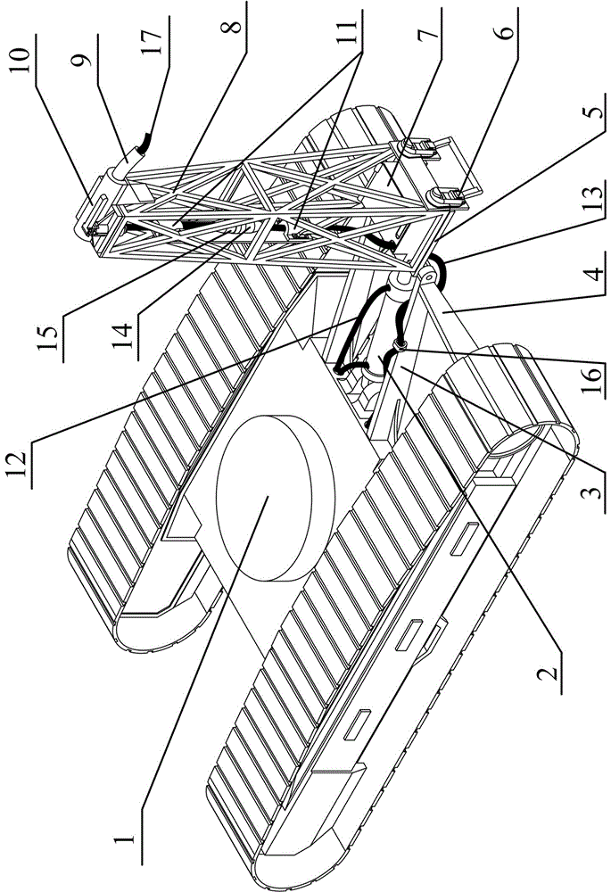
[0009] like figure 1 As shown, the present invention is a special walking frame for a pure electric hydraulic excavator, consisting of a walking frame 1, a hydraulic cylinder 2, a main support beam 3, an auxiliary support beam 4, a branch frame base 5, a branch frame connection device 6, a storage box 7, Branch frame 8, anti-fatigue rubber sleeve 9, cable locking device 10, cable fixing splint 11, hydraulic pipe 12, one end of the main support beam 3 is connected to the end of the walking frame 1, and one end of the auxiliary support beam 4 is connected to the outside of the end cover of the driving device , the main support beam 3 is connected to the end of the auxiliary support beam 4, the hydraulic pipe 12 protrudes from the end of the walking frame 1, and is connected to the hydraulic cylinder 2, the cylinder body of the hydraulic cylinder 2 is hinged to the end of the walking frame 1, and the piston rod is connected to the base of the branch frame 5 The bottom is hinged, ...


PUM


Abstract

The invention discloses a special travelling frame for a pure electric hydraulic excavator. One end of a primary supporting beam (3) is welded at the tail end of a travelling frame (1); one end of a secondary supporting beam (4) is welded at the outer side of a caterpillar drive motor end cover; the primary supporting beam (3) is connected with the tail end of the secondary supporting beam (4); a hydraulic pipe (12) extends out from the tail end of the travelling frame (1), and is connected to a hydraulic cylinder (2); a cylinder body of the hydraulic cylinder (2) is hinged with the tail end of the travelling frame (1); a piston rod of the hydraulic cylinder (2) is hinged with the bottom of a branch line rack base (5); one end of the branch line rack base (5) is hinged with the primary supporting beam (3); the other end of the branch line rack base (5) is equipped with a branch line rack connecting device (6); a line storage box (7) is arranged at the upper end of the branch line rack base (5); a branch line rack (8) is mounted at the upper end of the branch line rack base (5) through the branch line rack connecting device (6); a cable fixing clamping plate (11) is mounted inside the branch line rack (8); a cable locking device (10) is mounted on the top of the branch line rack (8); and an anti-fatigue rubber sleeve (9) gets out from the cable locking device (10).

Description

technical field [0001] The invention relates to the field of hydraulic technology, in particular to professional equipment for electric hydraulic excavators. Background technique [0002] Existing hydraulic excavators are generally driven by diesel fuel. This driving method not only consumes a lot of energy, but also has problems such as polluting the environment, loud noise, and narrow working temperature range. The pure electric hydraulic excavator solves many problems existing in the oil-powered excavator, and has broad development prospects. Existing electro-hydraulic excavators usually use a power supply method in which the battery and the excavator are separated. However, this power supply method has problems such as easy abrasion of the cable when mopping the ground, easy breaking of the cable when the excavator is walking, and inconvenient retraction of the cable. [0003] In the prior art, the name "Automatic Cable Retraction System for Pure Electric Hydraulic Exca...

Claims


Application Information

Patent Timeline
IPC IPC(8): E02F9/00
CPCE02F9/00
Inventor 冀宏陈乾鹏李浩黄路路龙小平张建樊新建王之君崔腾霞韦春晖
Owner LANZHOU UNIVERSITY OF TECHNOLOGY
Why Eureka
Try Eureka