

Reinforced plate type fire control joint structure for space structure
A technology of space structure and node structure, which is applied in the direction of building structure and construction, can solve the problems of lack of structural force, integrated design concept of building fire prevention, failure to expand the service building site of aluminum alloy reticulated shell structure, and inconvenience of construction, etc. , to achieve the effect of bending moment and shear force transmission and bearing capacity, uniform product quality and optimized construction
- Summary
- Abstract
- Description
- Claims
- Application Information
AI Technical Summary
Problems solved by technology
Method used
Image

Examples
Embodiment 1
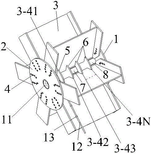
[0053] Example 1, such as Figure 8 As shown, the pipe 12 is fixed on the web 3-2 of an I-shaped section beam 3 through several fixing clips 13, and the six male card slots I5-1 of the chuck I5 correspond to the six I-shaped section beams 3 On the web 3-2, the first layer 3-41 female card slots 3-4 are inserted, and the six male card slots Ⅰ 5-1 are fixed to the six female card slots 3-4 of the first layer 3-41 respectively in a cross manner. The water outlet of the pipe 12 passes through the equipment hole I5-2 of the chuck I5 and is connected to the water inlet of the nozzle 11, and a cylindrical reinforcing ring II8 or a prismatic reinforcing ring II10 is set outside the nozzle 11, and the six I-shaped cross-section beams 3 are the first Layer 3-41 The web 3-2 sides below the female card groove 3-4 are respectively inserted into the six grooves Ⅱ8-2 of the cylindrical reinforcement ring Ⅱ8, and the flat port of the cylindrical reinforcement ring Ⅱ8 is pressed against the lo...
Embodiment 2
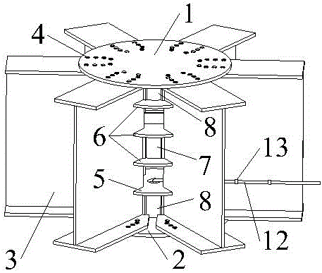
[0056] Example 2, such as Figure 9 As shown, the pipe 12 is fixed on the web 3-2 of an I-shaped section beam 3 through several fixing clips 13, and the six male card slots I5-1 of the chuck I5 correspond to the six I-shaped section beams 3 The first layer 3-41 of the web plate 3-2 is inserted into the female card slot 3-4, and the six male card slots Ⅰ 5-1 are respectively clamped and fixed with the six female card slots 3-4 in a criss-cross manner, and the outlet of the pipe 12 is passed through The equipment hole I5-2 of the chuck I5 is connected with the water inlet of the nozzle 11.
[0057] Insert the six male card slots II6-1 of the chuck II6 corresponding to the six I-shaped cross-section beams 3 webs 3-2 into the female card slots 3-4 of the fourth layer 3-44, and the six male card slots II6-1 are respectively connected to the first The 4-layer 3-44 female card slots 3-4 are clamped and fixed in a criss-cross manner.
[0058] Put a cylindrical reinforcing ring II8 o...
Embodiment 3
[0063] Example 3, such as Figure 10 As shown, the installation structure of embodiment 3 is basically the same as that of embodiment 2, except that at least one card is clamped and fixed in the female card slots 3-4 of the six I-shaped cross-section beams 3 between the chuck I5 and the chuck II6. Disk II6, if the chuck II6 is adjacent to the chuck II6, a cylindrical reinforcement ring I7 or a prism reinforcement ring I9 can be filled.
[0064] In this embodiment, a chuck II 6 is respectively inserted in the second layer 3-42 female card slot 3-4 of the six I-shaped cross-section beams 3 and the third layer 3-43 female card slot 3-4. 3-42 A cylindrical reinforced ring I7 or a prismatic reinforced ring I9 is filled between the female card slot 3-4 and the third layer 3-43 The female card slot 3-4, six I-shaped beams 3 The second layer 3-42 The web 3-2 sides between the female card slot 3-4 and the third layer 3-43 female card slot 3-4 are respectively inserted into the six g...
PUM
 Abstract
Description
Claims
Application Information