Environmental-friendly wall for electric power station
A power station and environmental protection technology, applied in the direction of walls, buildings, building components, etc., can solve the problems of high energy consumption, poor thermal insulation effect, and easily damaged walls of buildings, so as to reduce energy consumption, improve sound insulation, and improve sound insulation. Effect
- Summary
- Abstract
- Description
- Claims
- Application Information
AI Technical Summary
Problems solved by technology
Method used
Image

Examples
Embodiment 1
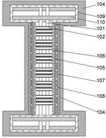
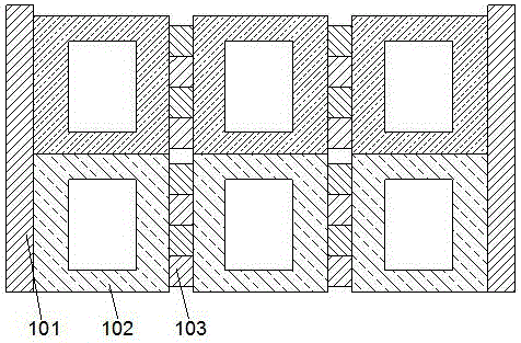
[0018] Such as figure 1 As shown, a power station environmental protection wall includes a hollow support frame 101 made of steel bars and a number of support tubes 102 arranged inside the support frame 101. The support frame is formed by crossing steel bars to form a grid structure with two layers inside and outside. , the two ends of the support tube are respectively plugged into the grid holes on the two-layer grid structure, the support tube 102 is arranged along the thickness direction of the support frame 101, so that the two ends of the support tube extend out of the support frame respectively Outside the two-layer grid structure, the support tube 102 is inserted into the rectangular cavity between the adjacent steel bars on the support frame 101, so that the support tube fills the two-layer grid structure, such as figure 2 As shown, the support tubes 102 are hollow quadrilateral structures, and the support tubes are arranged in a matrix, so that the outermost support ...
Embodiment 2
[0021] Grid-shaped grooves are provided on both ends of the support tube 102 , and the steel wire mesh frame 106 is clamped inside the corresponding grooves. By setting the groove, the steel wire constituting the steel wire grid is embedded in the groove, so that the steel wire grid can be kept stable relative to the support tube, and the steel wire grid is prevented from slipping from the support tube.
[0022] In order to improve the sound insulation effect, in this embodiment, the sound insulation sponge layers 105 on both sides are two layers arranged in parallel, and a sound insulation board 107 is respectively arranged between the two sound insulation sponge layers 105 . The sound insulation effect can be improved by setting 2 layers of sound-proof sponges, and the sound-proof sponges can be fixed conveniently by using the sound-proof boards arranged between the sound-proof foams. The sound-proof sponges can be bonded to the sound-proof boards, and structures such as embe...
Embodiment 3
[0025]In this embodiment, fixed brackets 109 are respectively provided on both sides of the support frame 101, so that the fixed brackets are used to fix the edge of the support frame. The fixed brackets 109 are made of steel bars, and the grid is formed by crossing the steel bars. structure, the fixed bracket 109 is a hollow structure, and the inner side of the fixed bracket 109 is provided with 2 layers of concrete slabs 110, so that the 2 layers of concrete slabs fill the space inside the fixed bracket, and the concrete slabs 110 are respectively provided with inserting When pouring the concrete slab, make the steel bars on the support frame extend into the inside of the fixed bracket, pour the concrete slab, and the steel bars can form a jack structure, and the steel bars that constitute the support frame 101 run through the fixed support 109 respectively. and inserted inside the sockets, the sockets on the two concrete slabs 110 are staggered from each other, by setting th...
PUM
 Abstract
Description
Claims
Application Information
 - R&D
- Intellectual Property
- Life Sciences
- Materials
- Tech Scout
- Unparalleled Data Quality
- Higher Quality Content
- 60% Fewer Hallucinations
Browse by: Latest US Patents, China's latest patents, Technical Efficacy Thesaurus, Application Domain, Technology Topic, Popular Technical Reports.
© 2025 PatSnap. All rights reserved.Legal|Privacy policy|Modern Slavery Act Transparency Statement|Sitemap|About US| Contact US: help@patsnap.com