Grouting device for steel shear structure assembling type building and construction method of grouting device

A grouting device and prefabricated technology, applied in the processing of building materials, construction, building components, etc., can solve the problems of reducing quality, affecting the beauty of the wall, labor and time and materials for the restoration of the wall, etc., to improve the strength and The effect of shear resistance and earthquake resistance, ensuring project quality and reducing labor intensity

Active Publication Date: 2017-02-15
曲周县和盛新型建筑材料有限公司
View PDF6 Cites 2 Cited by
  • Summary
  • Abstract
  • Description
  • Claims
  • Application Information

AI Technical Summary

Problems solved by technology

[0002] At present, the connection methods for the shear walls between the upper and lower floors of reinforced concrete shear wall prefabricated buildings mainly include reserved grouting hole connection and grouting plus threaded sleeve connection, reserved grouting hole and current use There are many disadvantages in the grouting and threaded sleeve: 1) The grouting hole is reserved for inserting ribs. When producing prefabricated shear wall panels, there are difficulties in manufacturing and polishing, and it is easy to be blocked in the hole; 2) Note The high cost of grout and threaded slee

Method used


Image

  • Grouting device for steel shear structure assembling type building and construction method of grouting device
  • Grouting device for steel shear structure assembling type building and construction method of grouting device
  • Grouting device for steel shear structure assembling type building and construction method of grouting device

Examples


Embodiment Construction

[0023] Below in conjunction with embodiment the present invention is described in further detail:

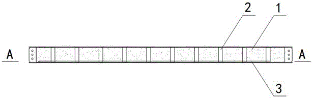
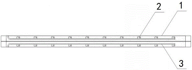
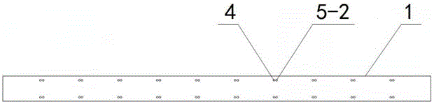
[0024] A grouting device for a prefabricated building with a steel shear structure, the structure of which is as follows Figure 1-4 As shown, it includes a grouting sleeve 2 arranged in the abdomen of the H steel beam 1, a grouting connecting pipe 3, an upper layer steel bar insertion hole 4 and a lower layer steel bar extension hole set on the upper flange of the H steel beam 1 5-2 and the lower reinforcement insertion hole 5-1 provided on the lower flange of the H steel beam 1, the upper reinforcement insertion hole 4, the lower reinforcement hole 5-2 and the lower reinforcement insertion hole 5-1 are all connected with the grouting Sleeve 2 is connected.

[0025] The grouting communication pipe 3 is fixedly arranged on the inner upper side of the lower flange plate of the H steel beam 1 , and the grouting sleeve 2 communicates with the grouting communication pipe 3 .

[00...


PUM


Abstract

The invention discloses a grouting device for a steel shear structure assembling type building and a construction method of the grouting device. The grouting device comprises grouting sleeves arranged in an H steel beam web, grouting communication pipes, reinforcing steel bar inserting holes, reinforcing steel bar stretching-out holes, and lower layer reinforcing steel bar inserting holes, wherein the reinforcing steel bar inserting holes and the reinforcing steel bar stretching-out holes are formed in an upper wing edge plate of an H steel beam, the lower layer reinforcing steel bar inserting holes are formed in a lower wing edge plate of the H steel beam, the two ends of the grouting sleeves are welded to the upper wing edge plate and the lower wing edge plate of the H steel beam; the reinforcing steel bar inserting holes and the reinforcing steel bar stretching-out holes of the upper wing edge plate and the lower layer reinforcing steel bar inserting holes of the lower wing edge plate are all communicated with the interiors of the grouting communication pipes, the grouting communication pipes are arranged on the inner upper side of the lower wing edge plate of the H steel beam, the grouting sleeves and the grouting communication pipes are communicated, and the aim that slurry is grouted into the grouting sleeves through one-position connection is achieved. The grouting device is simple in structure and novel in design, and facilitates industrialized production, the structural layout and the grouting method of interlayer reinforcing steel bar connecting sleeves are expanded, and the grouting construction speed and the grouting quality are improved.

Description

technical field [0001] The invention relates to a connection device and a construction method between shear walls of prefabricated buildings, in particular to a grouting device and a construction method of a steel shear structure prefabricated building. Background technique [0002] At present, the connection methods for the shear walls between the upper and lower floors of reinforced concrete shear wall prefabricated buildings mainly include reserved grouting hole connection and grouting plus threaded sleeve connection, reserved grouting hole and current use There are many disadvantages in the grouting and threaded sleeve: 1) The grouting hole is reserved for inserting ribs. When producing prefabricated shear wall panels, it is difficult to manufacture and polish, and it is prone to plugging in the hole; 2) Note The high cost of grout and threaded sleeves, the difficulty of making steel bars, the difficulty in positioning, and the large number of exposed grouting openings m...

Claims


Application Information

Patent Timeline
IPC IPC(8): E04G21/02E04B2/58
CPCE04B2/58E04G21/02
Inventor 和月河
Owner 曲周县和盛新型建筑材料有限公司
Why Eureka
Try Eureka