A low temperature heating system for a diesel engine

A diesel engine and heating system technology, applied to engine components, engine starting, machine/engine, etc., can solve the problems of reduced oil use time, incomplete diesel atomization, and inconvenience in life, so as to reduce exhaust emissions and effectively Conducive to environmental protection and the effect of saving oil cost

Active Publication Date: 2019-01-01
席瑾
View PDF7 Cites 1 Cited by
  • Summary
  • Abstract
  • Description
  • Claims
  • Application Information

AI Technical Summary

Problems solved by technology

One solution is to add diesel oil of different grades according to temperature changes, that is, high-grade diesel is used in low-temperature seasons, but compared with low-grade diesel, the durability of high-grade diesel is lower, and the price is higher, and the cost of use is greatly increased.
In addition, due to the inability of operators to respond accurately to temperature changes in a timely manner, high and low grade diesel oil is often mixed, resulting in incomplete atomization of diesel oil, resulting in insufficient combustion of the engine, high fuel consumption, and insufficient power.
Another measure is to use a blowtorch to bake the fuel tank, engine oil bottom and intake duct, which is not only time-consuming and laborious, it is easy to carbonize the engine oil bottom and reduce the use time of the oil, and there is a great potential safety hazard
The currently known solutions mostly focus on the low-temperature starting of the engine. In addition to their own shortcomings, these methods also ignore that when using diesel oil with a higher grade or an unstable grade, the diesel oil is also easy to condense during operation, causing Accidents occur due to failures such as flameout, which brings great inconvenience to people's lives

Method used


Image

  • A low temperature heating system for a diesel engine

Examples


Embodiment Construction

[0025] In order to make the technical means, creative features, goals and effects achieved by the present invention easy to understand, the present invention will be further described below in conjunction with specific illustrations.

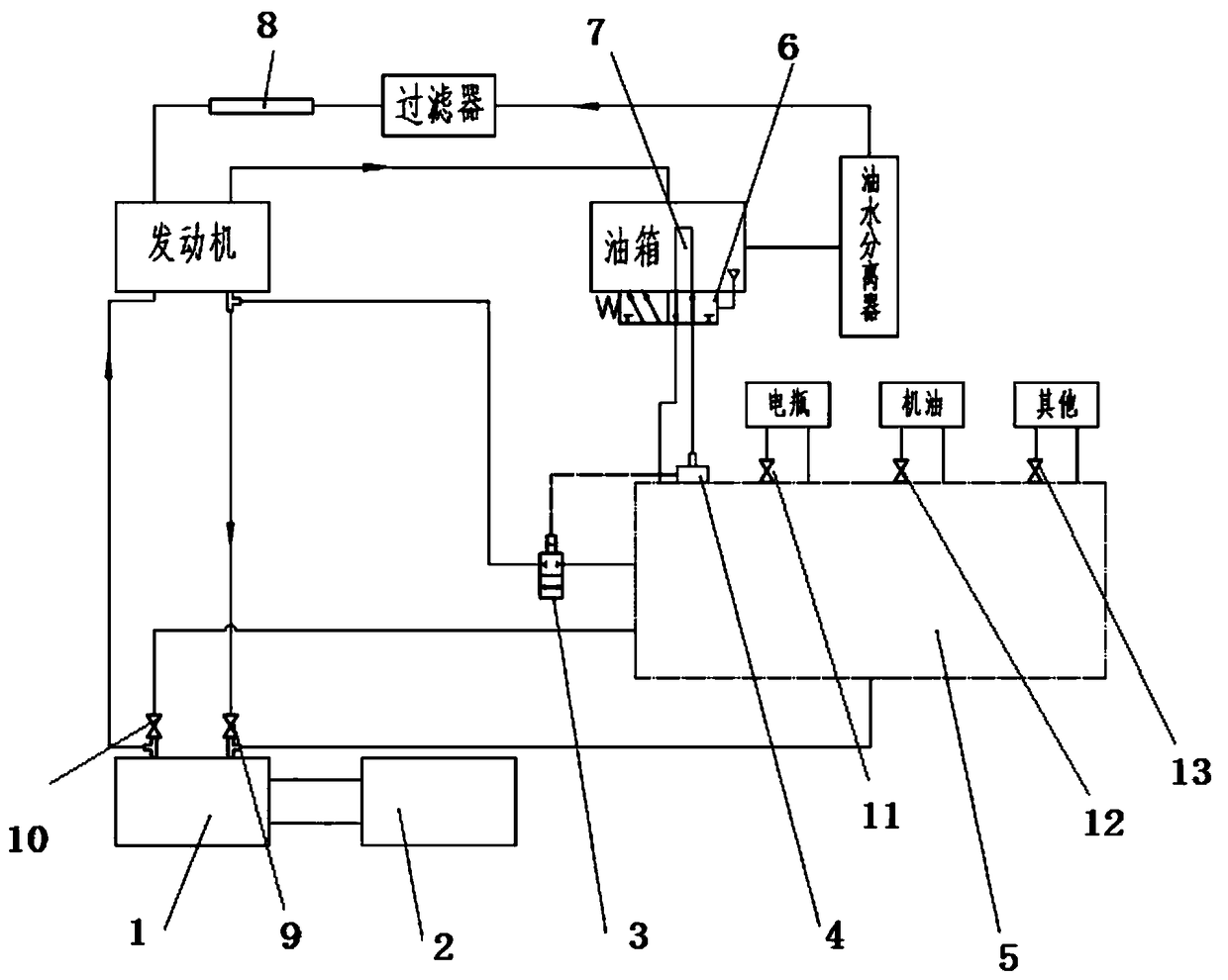
[0026] Refer to attached figure 1 , a low-temperature heating system for a diesel engine proposed by the present invention, including an engine, a fuel heater 1, a solenoid valve 3, a coolant leakage alarm 4, a distribution control valve block 5, a temperature sensing directional valve 6, a fuel tank heating device 7 and a pipe Road heating device 8, described pipeline heating device 8 is connected with the oil pump of described engine;

[0027] The fuel heater 1 is provided with a first shut-off valve 9 and a second shut-off valve 10. The engine water outlet is divided into two paths, one path is connected with the first shut-off valve 9, and the other path is connected with the solenoid valve 3. The first water inlet of the distribution contr...


PUM


Abstract

The present invention discloses a low-temperature heating system for a diesel engine. The system comprises an engine, a fuel heater, an electromagnetic valve, a coolant leakage alarm, a distribution control valve block, a temperature sensing directional valve, an oil tank heating device, and a pipe heating device. A first stop valve and a second stop valve are disposed on the fuel heater. A water outlet of the engine is divided into two passages with one being connected to the first stop valve and the other one being connected to a first water inlet of the distribution control valve block by means of the electromagnetic valve. The oil tank heating device is provided with the temperature sensing directional valve that has a control end connected with a temperature sensor. A first water outlet of the distribution control valve is connected to a temperature sensing directional valve of the oil tank heating device by means of the coolant leakage alarm. The pipe heating device is connected to an engine filter and an oil pump. The low-temperature heating system for a diesel engine effectively improves the viscosity and flowability of diesel oil at a low temperature to allow for sufficient combustion of the diesel oil, thereby ensuring that the diesel engine is started successfully and operates normally with achieved cost reduction and environmental protection.

Description

technical field [0001] The invention belongs to the field of diesel engine heating, and further relates to a diesel engine low-temperature heating system. Background technique [0002] Starting the diesel engine at low temperature in winter will accelerate the wear of the engine, and the exhaust emissions will be more serious than usual. The main reason for the difficulty in starting the engine at low temperature is the wax precipitation of diesel oil caused by the poor low temperature fluidity and evaporability of diesel oil itself. One solution is to add diesel oil of different grades according to temperature changes, that is, high-grade diesel is used in low-temperature seasons, but compared with low-grade diesel, the durability of high-grade diesel is lower, and the price is higher, which greatly increases the cost of use. In addition, due to the inability of operators to respond accurately to temperature changes in a timely manner, high and low grade diesel oil is ofte...

Claims


Application Information

Patent Timeline
Patent Type & Authority Patents(China)
IPC IPC(8): F02N19/04F02M31/16
CPCF02M31/16F02N19/04
Inventor 席瑾
Owner 席瑾
Why Eureka
Try Eureka