Method for producing a synchronizer ring

A technology of synchronizing rings and friction rings, applied in manufacturing tools, chemical instruments and methods, couplings, etc., can solve complex problems and achieve the effect of fewer production steps

Inactive Publication Date: 2017-02-15
DIEHL METAL STIFTUNG & CO KG
View PDF7 Cites 4 Cited by
  • Summary
  • Abstract
  • Description
  • Claims
  • Application Information

AI Technical Summary

Problems solved by technology

[0003] Known methods require a relatively large number of manufacturing steps and are complex

Method used


Image

  • Method for producing a synchronizer ring

Examples


Embodiment Construction

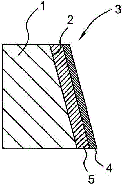
[0018] To produce the synchronizing ring, a ring body made of brass is used which has a conical connection surface on its inner circumference. Then, a friction ring is bonded to the connection surface by means of phenolic resin, said friction ring being formed from a composite material produced from a carbon fiber fabric impregnated with phenolic resin or another temperature-resistant adhesive. The friction ring has a first thickness D1 of eg 0.4-0.5 mm. Afterwards, the outer layer of the friction ring opposite the connection face is pyrolyzed by laser. For this purpose, the ring can be rotated and at the same time irradiated with laser light on the outer layer. For example, a laser can be a CO 2 Lasers, fiber lasers, Nd:YAG lasers, etc. The laser can have a laser energy power in the range of 2 kW.

[0019] The laser power and the treatment time period are selected in such a way that an outer layer with a second thickness D2 of 0.1-0.2 mm is produced.

[0020] The drawing...


PUM

PropertyMeasurementUnit
First thicknessaaaaaaaaaa
Second thicknessaaaaaaaaaa

Abstract

A method for producing a synchronizer ring includes providing a ring body (1) made of metal and having a conical connecting surface (2), providing a friction ring (3), corresponding to the connecting surface (2), made of a composite material of carbon fiber bound with a resin, adhesively bonding the friction ring (3) to the connecting surface (2), and pyrolysing exclusively an outer layer (4) of the friction ring (3) which is remote from the connecting surface (2).

Description

technical field [0001] The invention relates to a method for manufacturing a synchronizer ring according to claim 1 of the patent. Background technique [0002] Such a method is known from DE 103 34 895 B3. In a known method, friction rings made of composite material are pyrolyzed at 1100° C. in an inert gas atmosphere, so that a substantial portion of the resin is converted into atmospheric carbon. Then, the friction rings treated in this way are impregnated with resin again and the pyrolysis is repeated. Then, the carbon fibers and carbon produced during the pyrolysis process are fixed by impregnating them with resin. In a further manufacturing step, the friction ring is pressed. Finally, the friction ring produced in this way is glued to the connection face of the ring body. [0003] The known methods require a relatively large number of manufacturing steps and are complex. Contents of the invention [0004] The purpose of the present invention is to eliminate the ...

Claims


Application Information

Patent Timeline
IPC IPC(8): F16D23/04B29C70/00
CPCB29C70/00F16D23/04F16D2200/0078F16D2200/0082F16D2250/00F16D23/025F16D69/026F16D2250/0069F16D2300/12B32B37/12B32B37/14B32B2310/0825B32B2310/0843B23K26/0006F16D69/00
Inventor S·拉姆K·埃德曼M·德恩赫费尔
Owner DIEHL METAL STIFTUNG & CO KG
Why Eureka
Try Eureka