Air energy low-temperature liquefied gas non-pump filling system

A technology for low-temperature liquefied gas and filling system, which is applied in gas/liquid distribution and storage, equipment for loading pressure vessels, and methods for vessel discharge, etc., which can solve the problem of large floor space, increased operation and maintenance costs, and low reliability And other issues

Inactive Publication Date: 2017-02-15
张夏炎
View PDF0 Cites 5 Cited by
  • Summary
  • Abstract
  • Description
  • Claims
  • Application Information

AI Technical Summary

Problems solved by technology

[0005] 1. Energy consumption in the way of pumping: the power of cryopumps ranges from a dozen kilowatts to tens of kilowatts, and some sites even have to build dedicated substations for this purpose to meet the needs
Not only is the investment large, the area occupied is large, and there are many equipments, but the location of the construction site is also limited by the power supply, and the operation and maintenance costs are also increased;
[0006] 2. The operation and maintenance cost of the pump delivery method is high, the reliability is relatively low, and the service lif

Method used


Image

  • Air energy low-temperature liquefied gas non-pump filling system
  • Air energy low-temperature liquefied gas non-pump filling system
  • Air energy low-temperature liquefied gas non-pump filling system

Examples


Embodiment 1

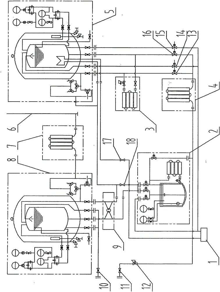
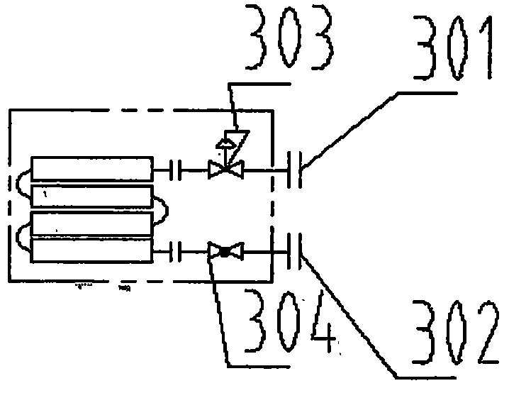
[0073] Embodiment 1: as figure 1 As shown, an air-energy low-temperature liquefied gas pumpless filling system includes a gas filling machine (1), a transfer tank (2), a supercharger (3), a temperature-increasing vaporizer (4), a high-pressure low-temperature storage tank ( 5), vent pipe (6), EAG vaporizer (7), low-pressure low-temperature storage tank (8), low-saturation heat exchanger (9), etc.

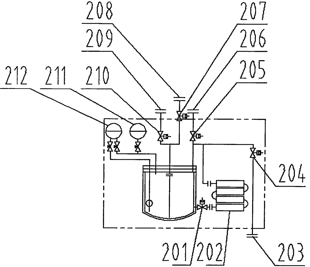
[0074] The transfer tank (2) is an external cold-preservation container, and the transfer tank (2) is the core to realize the conversion of low-temperature and low-pressure liquefied gas to high-pressure, that is, transfer low temperature from the low-pressure and low-temperature storage tank (8) to the high-pressure and low-temperature storage tank (5). The liquefied gas is realized through the transfer tank (2). The transfer tank (2) is at least provided with four openings: a transfer tank boost port (203), a transfer tank pressure relief port (206), a transfer tank liquid inlet ...

Embodiment 2

[0088] Embodiment 2: All gasifiers in the system (such as: booster (3), temperature-increasing gasifier (4), EAG gasifier (7), transfer tank booster (202), etc.) can be empty The warm type absorbs air energy to heat and pressurize; it can also be heated by steam or other heat media to provide energy to heat and pressurize. Others are with embodiment 1.

Embodiment 3

[0089] Embodiment 3: The transfer tank (2) can be connected in parallel with multiple corresponding interfaces, such as connecting the liquid outlets (209) of each transfer tank together and then connecting to the system; connecting the liquid inlets (208) of each transfer tank together Connect to the system again; connect the booster ports (203) of the transfer tanks together and then connect to the system; connect the pressure relief ports (206) of the transfer tanks together and then connect to the system. The working steps of each group of transfer tanks (2) are carried out alternately. Others are with embodiment 1.


PUM


Abstract

The invention discloses an air energy low-temperature liquefied gas non-pump filling system. According to the non-pump filling system, when gas is added into a gas cylinder from a low-temperature liquefied gas station, no pump is required, and pressurization of low-temperature liquefied gas storage equipment is not required, either. The temperature difference of low-temperature liquefied gas and air can be used for absorbing air energy, the low-temperature liquefied gas or high-pressure gas is filled into a high-pressure gas cylinder, and the temperature and pressure of low-temperature liquid inside the low-temperature liquefied gas storage equipment are scarcely increased due to gas addition. Energy consumption is reduced, and the building cost and the using and maintaining cost of gas station system equipment are also reduced, and therefore operation is safer and more reliable.

Description

technical field [0001] The present invention relates to the field of pump-less filling of low-temperature liquefied gas, in particular, relates to filling low-temperature gas cylinders with low-temperature gas cylinders without cryogenic pumps or gasifying low-temperature gas cylinders with high-pressure gas cylinders without pumps or pumps. The pipeline provides a system of normal temperature gas at a certain pressure. Such as liquid oxygen, liquid nitrogen, liquid argon, liquid hydrogen, liquid helium, liquefied natural gas (LNG) filling stations and filling stations, and gasification stations, especially LNG vehicle filling stations. Background technique [0002] Cryogenic liquefied gas is a gas that exists in liquid form, and it is to cool down and liquefy the gas for the needs of storage and transportation. It has a low temperature (generally between -162°C and -256°C under normal pressure), a large gas-liquid ratio (that is, the volume ratio of a unit volume of low-te...

Claims


Application Information

Patent Timeline
IPC IPC(8): F17C5/02F17C13/00
Inventor 张夏炎
Owner 张夏炎
Why Eureka
Try Eureka