Check patentability & draft patents in minutes with Patsnap Eureka AI!

Numerical control machine tool CNC machining system

A processing system, CNC machine tool technology, applied in general control system, control/adjustment system, program control, etc., can solve the problem of inability to optimize control of machine tool spindle plus process parameters, tool wear, damage, and inability to monitor and deal with machine tool vibration in real time And other issues

Inactive Publication Date: 2017-02-15
天津现东机电有限公司
View PDF0 Cites 1 Cited by
  • Summary
  • Abstract
  • Description
  • Claims
  • Application Information

AI Technical Summary

Problems solved by technology

[0003] The present invention provides a CNC machining system of a numerically controlled machine tool to solve the problems in the prior art presented in the above-mentioned background technology. Monitoring and processing, and at the same time, the problem of not being able to perform real-time optimal control of processing parameters such as the spindle speed and feed rate of the machine tool

Method used


Image

  • Numerical control machine tool CNC machining system

Examples


Embodiment

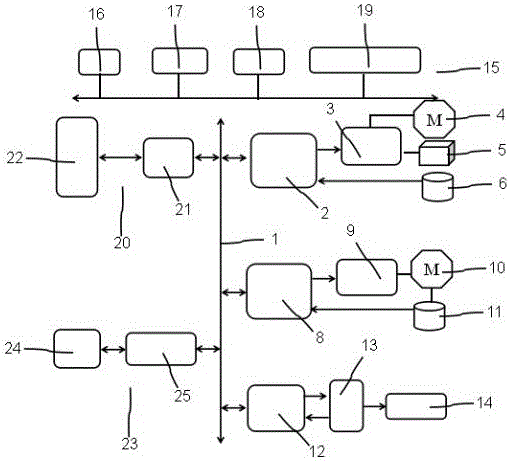
[0019] This embodiment: as figure 1 As shown, a CNC machining system of a numerically controlled machine tool 14 includes a CNC machining system bus 1, the CNC machining system bus 1 communicates with the feed axis position control system interface 2, and the output of the feed axis position control system interface 2 is connected to the speed Servo system 3, the output of the speed servo system 3 is connected to the servo motor 4 and the manufacturing machine 5, the servo motor 4 and the manufacturing machine 5 are respectively output to the first photoelectric encoder 6, and the first photoelectric encoder 6 feedbacks the output In feed axis position control system interface 2;

[0020] The CNC machining system bus 1 communicates with the spindle control system interface 8, the output of the spindle control system interface 8 is connected to the spindle drive device 9, the spindle drive device 9 is connected to the spindle motor 10, and the spindle motor 10 is connected to t...


PUM


Abstract

The invention belongs to the technical field of a CNC machining system, and especially relates to a numerical control machine tool CNC machining system. A CNC machining system bus is communicated with a feed shaft position control system interface; the output of the feed shaft position control system interface is connected to a velocity servo system; the output of the velocity servo system is connected to a servo motor and a manufacturing machine; the servo motor and the manufacturing machine are output to a first photoelectric encoder; and the first photoelectric encoder is fed back and output to the feed shaft position control system interface. The numerical control machine tool CNC machining system solves the problems that, in the prior art, since most of the CNC machining mainly adopts the distributed processing, tool wear and damage and machine tool machining vibration and the like cannot be subjected to real-time monitoring and processing, and meanwhile, technological parameters of machine tool spindle rotation speed and feed amount and the like cannot be subjected to real-time optimization control, and has beneficial technical effects of real-time optimization control, improving functionality of the CNC machining system, realizing position control of the CNC machining system and improving processing capacity for a plurality of signals.

Description

technical field [0001] The invention belongs to the technical field of numerical control machine tool systems, and in particular relates to a CNC machining system of a numerical control machine tool. Background technique [0002] CNC machining refers to the various movements that the control system issues instructions to make the tool meet the requirements, and expresses the technical requirements and processing technology requirements such as the shape and size of the workpiece in the form of numbers and letters. It generally refers to the processing of parts on CNC machine tools. In the process of processing, a CNC machine tool is a machine tool controlled by a computer. The computer used to control the machine tool, whether it is a special computer or a general-purpose computer, is collectively referred to as a CNC system. The movement and auxiliary actions of the CNC machine tool are controlled by the CNC machine tool. The instructions issued by the system, and the instr...

Claims


Application Information

Patent Timeline
IPC IPC(8): G05B19/402
CPCG05B19/402
Inventor 宋付伟王金桥宋付春柳金波
Owner 天津现东机电有限公司
Features
  • R&D
  • Intellectual Property
  • Life Sciences
  • Materials
  • Tech Scout
  • Unparalleled Data Quality
  • Higher Quality Content
  • 60% Fewer Hallucinations
Learn More