Dual-axis tracking type photovoltaic or photo-thermal support

A two-axis tracking, photothermal technology, applied in the direction of use feedback control, etc., can solve the problems of strong volatility, short service life, damage to surface vegetation, etc., to improve the absorption efficiency and duration, the overall structure is simple and stable, and the adjustment method simple and accurate effect

Active Publication Date: 2017-02-15
杨大楼
View PDF10 Cites 14 Cited by
  • Summary
  • Abstract
  • Description
  • Claims
  • Application Information

AI Technical Summary

Problems solved by technology

The shortcomings of the steel frame installed on the ground are: 1. It occupies a large area, and the installation of the rigid support has high requirements on the ground conditions, destroying the vegetation on the ground, consuming a large amount of steel, and high cost
2. The fluctuation is strong. During the non-noon period, the protective glass of the front panel of the photovoltaic panel and the photothermal tube reflects the sunlight, which leads to the short power generation time and low efficiency of the photovoltaic panel and the photothermal tube.
3. The tracking system in the existing photovoltaic / photothermal support mostly uses gear transmission structure, push rod connecting rod structure, hydraulic cylinder or bearing, etc. The gear and push rod connecting rod structure are easy to be damaged by the vibration of the support when used in the field. The lubrication requirements of the hydraulic system and bearings are high, the installation and maintenance costs are high, and the service life is short
[0003] Chinese patent CN205336197U discloses a flexible bracket with adjustable inclination angle. The flexible bracket can only realize single-axis tracking, but cannot realize dual-axis tracking, and the power generation efficiency is low; because the flexible bracket drives the adjustable tilt angle fixing device to rotate through the crank connecting rod driving device , the deceleration mechanism and multi-stage connecting rod in the adjustable inclination fixing device are rigidly connected to the photovoltaic platform, and there is interference and impact damage between the wind-induced beating of the flexible steel cable and the movement of the motor, which makes the flexible support unable to work stably and cannot Application in practical engineering
At the same time, the flexible support does not solve the problem of flexible cables sagging caused by the gravity of the flexible cables, photovoltaic panels and photothermal tubes, the problem of jumping and swinging of flexible cables in bad weather, and the problems of steel cables caused by temperature changes in spring, summer, autumn and winter. Structural stability problems caused by thermal expansion and contraction

Method used


Image

  • Dual-axis tracking type photovoltaic or photo-thermal support
  • Dual-axis tracking type photovoltaic or photo-thermal support
  • Dual-axis tracking type photovoltaic or photo-thermal support

Examples


Embodiment 1

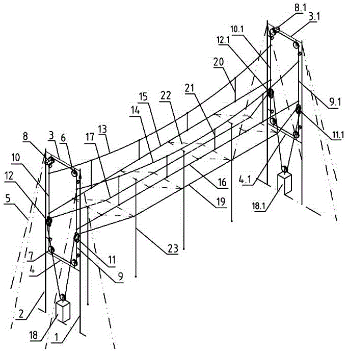
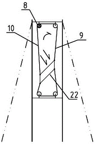
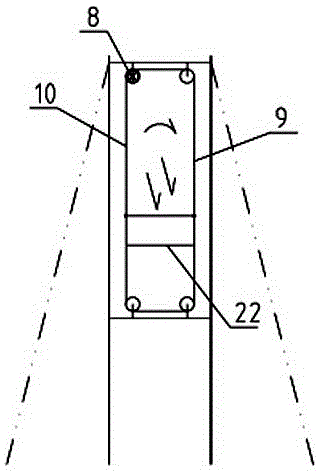
[0028] Such as Figure 1-6 As shown, the dual-axis tracking photovoltaic or photothermal support of the present invention includes a left bearing frame and a right bearing frame arranged longitudinally at intervals from north to south, the left bearing frame is located on the north side, and the right bearing frame is located on the south side; the left bearing frame The frame and the right bearing frame have the same structure, including:

[0029] The front column 1 and the rear column 2 are arranged at intervals along the transverse direction, and the front and rear columns 1 and 2 are connected by the upper beam 3 and the lower beam 4 to form a rectangular frame. The support cable 5 is auxiliary fixed, and is used to offset the load tension on the upper and lower beams 3 and 4; a flexible cable slewing unit is arranged in the rectangular frame, and the flexible cable slewing unit is composed of two fixed pulleys respectively arranged on the upper beam 3 6 and two fixed pul...

Embodiment 2

[0038] Such as Figure 7 As shown, the structure of the dual-axis tracking photovoltaic or photothermal support described in this embodiment is the same as that in Embodiment 1, and also includes a left bearing frame and a right bearing frame arranged longitudinally from north to south, and the left bearing frame is located on the north side , the right bearing frame is located on the south side; the left and right bearing frames have the same structure. The difference between this embodiment and Embodiment 1 is that four flexible cable slewing units are arranged in the rectangular frame to form an array platform to expand the scale, and then a large-scale dual-axis tracking photovoltaic / photovoltaic system is formed by cascading multiple above-mentioned platforms. thermal power station.


PUM


Abstract

The invention discloses a dual-axis tracking type photovoltaic or photo-thermal support. The support includes left and right bearing frame arranged at two ends of a longitudinal direction, a flexible cable rack is arranged between corresponding flexible cable rotation units on the left and right bearing frames, the flexible cable rack includes sag cables, first horizontal load cables and second horizontal load cables which are arranged on the front and rear side vertical cable bodies of corresponding rectangular flexible cable frames of the left and right bearing frames from top to bottom; two ends of the sag cables and the first horizontal load cables are fixed to the front and rear side vertical cable bodies of the corresponding rectangular flexible cable frames, and two ends of the second horizontal load cables bypass lifting fixed pulleys on the front and rear side vertical cable bodies of the corresponding rectangular flexible cable frames to be connected with a corresponding lifting driving device; and a plurality of droppers are arranged between the sag cables located on the front and rear side vertical cable bodies of the rectangular flexible cable frames and the first horizontal load cables at intervals along a longitudinal direction. The dual-axis tracking type photovoltaic or photo-thermal support provided by the invention is simple and stable in overall structure, low in cost, and simple and accurate to adjust, and is suitable for engineering popularization and application.

Description

technical field [0001] The invention relates to a photovoltaic or photothermal support, in particular to a dual-axis tracking photovoltaic or photothermal support. Background technique [0002] With the increasingly tense energy supply and global carbon emission restrictions, solar energy, as an inexhaustible clean energy, is expanding its application fields. Solar photovoltaic power generation and solar thermal power generation are the mainstream development directions of solar energy applications. At present, solar photovoltaic power generation and photothermal power generation mostly adopt the method of installing steel frames on the ground to support photovoltaic panels and photothermal tubes. The shortcomings of the steel frame installed on the ground are: 1. It occupies a large area, and the installation of the rigid support has high requirements on the ground conditions, destroying the vegetation on the ground, consuming a large amount of steel, and high cost. 2. Str...

Claims


Application Information

Patent Timeline
Patent Type & Authority Applications(China)
IPC IPC(8): G05D3/12
CPCG05D3/12Y02E10/50
Inventor 杨大楼
Owner 杨大楼
Why Eureka
Try Eureka