
Centralized bus timing control method based on time slice planning

A bus timing and control method technology, applied in the bus network, data exchange through path configuration, digital transmission system, etc., can solve the problems of unpredictable system operation status chain reaction, unpredictable system behavior, system real-time performance degradation, etc. , to achieve the effect of satisfying the amount of satellite data interaction, strong real-time performance, and high real-time performance

Active Publication Date: 2017-02-15
BEIJING INST OF CONTROL ENG
View PDF6 Cites 1 Cited by
  • Summary
  • Abstract
  • Description
  • Claims
  • Application Information

AI Technical Summary

Problems solved by technology

In the traditional spacecraft bus communication design, the event-based bus message frame transmission method is mainly used. This method has two limitations: 1) The real-time performance is not strong
BC initiates a message frame to RT triggered by an event. The creation, sending and receiving of data is obviously aperiodic. For messages of different lengths, the difference in transmission time will lead to a decrease in real-time performance of the system.
2) System behavior is unpredictable
The central control calculation reads the input, and the output control instructions are realized through the 1553B bus message. If the message communication is not created, sent and received according to a fixed time point, the execution time from input to output during the program running will be uncertain. , the operating state of the system will also become unpredictable due to the "chain reaction"

Method used


Image

  • Centralized bus timing control method based on time slice planning
  • Centralized bus timing control method based on time slice planning
  • Centralized bus timing control method based on time slice planning

Examples


Embodiment Construction

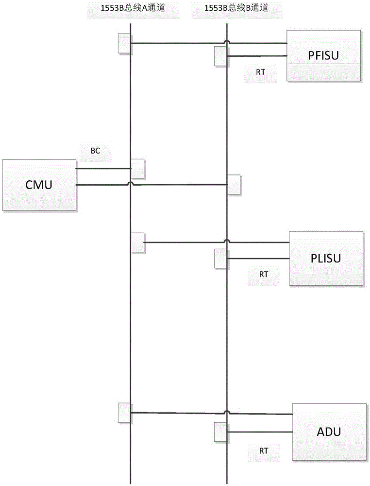
[0039] A satellite integrated electronic system is composed of a central management unit CMU, a platform service unit (PFISU), a load service unit (PLISU), and an actuator drive unit (ADU). Each single unit communicates through the 1553B bus. The CMU is the core of the integrated electronic system. As the bus controller (BC) initiates data communication, other stand-alone computers act as remote terminals (RT) to respond to data commands and reply. The onboard application software of the integrated electronic system realizes the function of the bus controller and regularly communicates with each RT terminal to complete the data management of the integrated electronic system. The network topology is such as figure 1 As shown, the specific requirements are as follows:

[0040] 1. The CMU application software control cycle is 64ms, that is, data management is performed every 64ms. The communication cycle must be divided by the control cycle as the time slice. A control cycle contain...


PUM


Abstract

The invention discloses a centralized bus timing control method based on time slice planning. The method comprises the following steps: a step of sending a fast frame message to an ADU on a comprehensive satellite electronic system; a step of reading closed loop feedback data sent back by the ADU from a BC message stack after delaying for 1.6ms; a step of sending message frames of a type A and or message frames a type B according to 64ms cycle count CNT1 and 448ms cycle count CNT2; a step of reading telemeasuring data sent back a RT from a BC message stack within a next control period; and a step of performing bus fault judgment by using CMU software within each control period, judging a bus communication state of BC and RT according to a RT message state character, and switching from a bus A to a bus B. According to the centralized bus timing control method disclosed by the invention, the bus operation is strictly controlled within one control period, thereby avoiding temporary message frame reception and transmission caused by emergency, improving the communication instantaneity of the system, reducing the bus load and ensuring the predictability of the operation state of the system.

Description

Technical field [0001] The invention relates to a centralized bus timing control method based on time slice planning, which belongs to the field of embedded software and is suitable for the design of the communication architecture of onboard application software of a comprehensive electronic system. Background technique [0002] In the spacecraft (satellite or spacecraft) 1553B bus network, the central control computer acts as a bus controller (BC) to initiate data communication, and other single machines act as remote terminals (RT) to respond to data commands and respond. In the traditional spacecraft bus communication design, the event-based bus message frame transmission method is mainly used. This method has two limitations: 1) The real-time performance is not strong. The BC initiates a message frame to the RT triggered by an event. The creation, sending and receiving of data is obviously non-periodic. For messages of different lengths, the difference in transmission time wi...

Claims


Application Information

Patent Timeline
IPC IPC(8): H04L12/40
CPCH04L12/40013H04L2012/4028
Inventor 杨春河万丽景王健蓉李经松王振华曹志威董晓刚陈朝晖王玉峰吕楠
Owner BEIJING INST OF CONTROL ENG
Learn More