
Draught fan dewaterer and boiler room

A technology of induced draft fan and dehydrator, which is applied in the field of boilers and can solve problems such as short service life, violent vibration of induced draft fan, and corrosion

Inactive Publication Date: 2017-02-22
XINJIANG NORTH TIANHENG ENERGY SAVING TECH CO LTD
View PDF8 Cites 1 Cited by
  • Summary
  • Abstract
  • Description
  • Claims
  • Application Information

AI Technical Summary

Problems solved by technology

[0003] The present invention provides an induced draft fan dehydrator and a boiler room, which overcomes the deficiencies of the prior art and can effectively solve the problems of rust, corrosion and short service life of the induced draft fan in the process of dust removal and desulfurization of existing coal-fired boilers , and the eccentric rotation of the impeller, resulting in severe vibration of the induced draft fan, which can only be shut down for maintenance or replacement of the impeller, which affects the normal production of the enterprise

Method used


Image

  • Draught fan dewaterer and boiler room
  • Draught fan dewaterer and boiler room
  • Draught fan dewaterer and boiler room

Examples


Embodiment 1

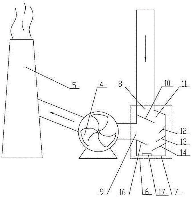
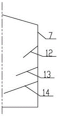
[0023] Embodiment one: as attached figure 2 , 3 , 4, the induced draft fan dehydrator 6 includes a tank body 7, the upper end of the tank body 7 is provided with a flue gas inlet 8, the left side of the tank body 7 is provided with a flue gas outlet 9, and the tank body above the flue gas outlet 9 The left inner wall of 7 is provided with a deflector 10 with a high left and a low right, and a flue gas passage 11 is formed between the upper end surface of the deflector 10 and the right inner wall of the tank body 7 . In the present invention, a tank body 7 is added on the pipeline before the entrance of the induced draft fan 4, the flue gas inlet 8 of the tank body 7 communicates with the pipeline, and the flue gas outlet 9 of the tank body 7 communicates with the inlet of the induced draft fan 4. An inclined deflector 10 is installed on the inner wall of the tank body 7 below the inlet 8 and above the flue gas outlet 9, thereby changing the direction of the flue gas flow, so...

Embodiment 2

[0031] Embodiment two: as attached Figure 5 As shown, a boiler room includes boiler 1, dust remover 2, desulfurization equipment 3, induced draft fan 4, chimney 5, and induced draft fan dehydrator 6 in the above technical solution. The smoke inlet of the device 2 is connected, the smoke outlet of the dust collector 2 is connected with the smoke inlet of the desulfurization equipment 3 through the pipeline, and the smoke outlet of the desulfurization equipment 3 is connected with the flue gas inlet 8 of the tank body 7 through the pipeline, and the tank body 7 The flue gas outlet 9 is communicated with the inlet of the induced draft fan 4 through a pipeline, and the outlet of the induced draft fan 4 is communicated with the inlet of the chimney 5 through a pipeline. The tank body 7 of the induced draft fan dehydrator 6 is welded and installed with the pipeline, and the tank body 7 is customized according to the size of the induced draft fan 4 specification and the pipeline.


PUM


Abstract

The invention relates to the technical field of boilers, in particular to a draught fan dewaterer and a boiler room. The draught fan dewaterer comprises a tank, a smoke inlet is arranged at the upper end of the tank, a smoke outlet is arranged on the left side of the tank, a flow guide plate with a high left side and a low right side is arranged on the inner wall of the left side, above the smoke outlet, of the tank, and a smoke channel is formed between the upper end face of the flow guide plate and the inner wall of the right side of the tank. The draught fan dewaterer is mounted in front of a draught fan, and comprises the flow guide plate, a dewatering pore plate and a mud guard which are mounted in the tank; the flow guide plate and the dewatering pore plate work together to enable smoke, passing through the flow guide plate and the dewatering pore plate, to form 'S'-shaped rotational flow, and vapor, dust and acid are separated from the smoke according to the centrifugal principle, so that rusting and corrosion of the draught fan are avoided, the service life of the draught fan is prolonged, and working stability of the draught fan is improved; the dust is prevented from being adsorbed onto blades, eccentric rotation of impellers is avoided, normal production of enterprises is guaranteed, and maintenance cost is reduced.

Description

technical field [0001] The invention relates to the technical field of boilers, and relates to an induced draft fan dehydrator and a boiler room. Background technique [0002] At present, whether it is a thermal power plant or a central heating boiler room using a coal-fired boiler, dust removal and desulfurization must meet the emission standards set by the national and local environmental protection departments. The dust removal and desulfurization of enterprises using coal-fired boilers in China basically follow the attached regulations. figure 1 The process shown is restricted by various factors. Most of the desulfurization uses wet desulfurization equipment. The flue gas discharged from the boiler 1 passes through the dust collector 2 and the desulfurization equipment 3, and is extracted by the induced draft fan 4, and is discharged into the atmosphere through the chimney 5. , see attached figure 1 The sulfide in the high-temperature flue gas (above 100°C) entering th...

Claims


Application Information

Patent Timeline
IPC IPC(8): B01D45/16B01D53/26F23J15/00F23J15/02
CPCB01D45/16B01D53/26F23J15/006F23J15/02F23J15/022
Inventor 李微毛建涛
Owner XINJIANG NORTH TIANHENG ENERGY SAVING TECH CO LTD
Learn More