Gas-solid separator, as well as denitration and dust-removing device

A gas-solid separator, denitrification and dust removal technology, applied in separation methods, dispersed particle separation, gas treatment, etc., can solve the problems of damage to catalysts, ash accumulation, and increase of flue gas flow rate in catalyst holes, so as to increase flow speed, enhance Service life, the effect of increasing the denitration effect

Active Publication Date: 2017-02-22
SHANDONG TIANLI ENERGY SAVING ENG
View PDF6 Cites 5 Cited by
  • Summary
  • Abstract
  • Description
  • Claims
  • Application Information

AI Technical Summary

Problems solved by technology

[0006] Therefore, the fly ash in the flue gas directly affects the service life of the catalyst
[0007] However, in the SCR denitrification equipment in the prior art, the concentration of fly ash in the flue gas is relatively high, and it is easy to accumulate ash on the surface of the catalyst in the denitrification reactor, especially the fly ash with large particles is easy to block the internal voids of the catalyst and increase the amount of smoke in the catalyst pores. gas flow rate, exacerbating the rate of catalyst attrition and ultimately damaging the catalyst

Method used


Image

  • Gas-solid separator, as well as denitration and dust-removing device
  • Gas-solid separator, as well as denitration and dust-removing device
  • Gas-solid separator, as well as denitration and dust-removing device

Examples


Embodiment Construction

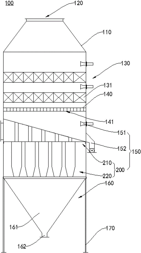
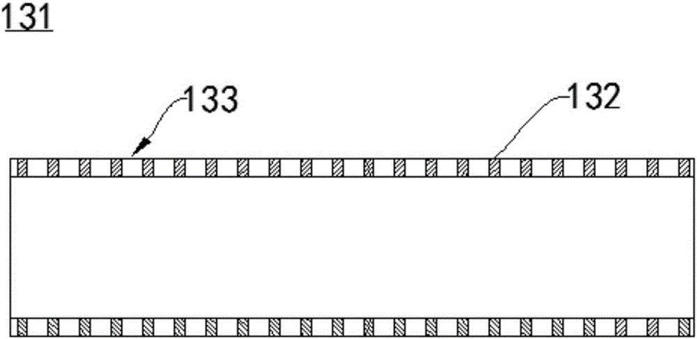
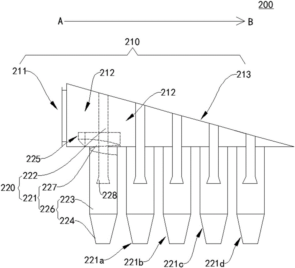
[0031] In order to make the purpose, technical solutions and advantages of the embodiments of the present invention clearer, the technical solutions in the embodiments of the present invention will be clearly and completely described below in conjunction with the drawings in the embodiments of the present invention. Obviously, the described embodiments It is a part of embodiments of the present invention, but not all embodiments. The components of the embodiments of the invention generally described and illustrated in the figures herein may be arranged and designed in a variety of different configurations. Accordingly, the following detailed description of the embodiments of the invention provided in the accompanying drawings is not intended to limit the scope of the claimed invention, but merely represents selected embodiments of the invention. Based on the embodiments of the present invention, all other embodiments obtained by persons of ordinary skill in the art without cre...


PUM


Abstract

The invention relates to environmental protection equipment and a denitration and dust-removing device, in particular to a gas-solid separator, as well as a denitration and dust-removing device. The gas-solid separator comprises a smoke gas distribution chamber. The smoke gas distribution chamber is provided with a smoke gas inlet for introducing a to-be-separated gas in a first direction; a plurality of gas cavities which are communicated mutually are distributed in the smoke gas distribution chamber in the first direction; and the volume of the plurality of the gas cavities is gradually reduced in the first direction. The smoke gas distribution chamber is connected with a plurality of cyclone separation assemblies which are in one-to-one correspondence with the plurality of gas cavities; each separation assembly comprises a cyclone cylinder and a gas discharge pipe which are matched mutually; the cyclone cylinder is provided with a gas inlet and flow guide end which is used for input gas and positioned in the gas cavities; and the gas discharge pipe partially stretches into the cyclone cylinder and penetrates through the smoke gas separation chamber. The denitration and dust-removing device comprises a shell and the gas-solid separator. The gas-solid separator, as well as the denitration and dust-removing device, protects a catalyst and prolongs the service life of the catalyst to finally realize the technical effects of improving the denitration effect and reducing the cost.

Description

technical field [0001] The invention relates to environmental protection equipment, which is a denitration and dust removal device, in particular a gas-solid separator and the denitration and dust removal device. Background technique [0002] Selective Catalytic Reduction of NOx (SCR denitrification process for short) is one of the more commonly used flue gas denitrification technologies at present. The boiler flue gas is sprayed into the denitrification reducing agent, and under the action of the catalyst, the NOx in the flue gas is reduced to harmless N2 and H2O to achieve the purpose of NOx removal. [0003] The main factor affecting the denitrification performance of the SCR method is the catalyst, and the factor affecting the catalyst is the activity of the catalyst. The main reason for the loss of catalyst activity is that the catalyst is poisoned by certain components in the flue gas during the actual operation of the SCR device. , Catalyst sintering due to high flue...

Claims


Application Information

Patent Timeline
IPC IPC(8): B01D45/16B01D45/18B01D53/86B01D53/56
CPCB01D45/16B01D45/18B01D53/8631B01D2258/0283
Inventor 刁志芹张文学刁志峰
Owner SHANDONG TIANLI ENERGY SAVING ENG
Why Eureka
Try Eureka