Membrane filtration unit and membrane assembly

A filtration unit, membrane filtration technology, applied in membrane, membrane technology, semi-permeable membrane separation, etc., can solve the problems of shortening the service life of the membrane stack, aggravating the pollution degree of the membrane, reducing the water treatment efficiency, etc., and increasing the contact area. , the structure is simple, the effect of increasing the number

Pending Publication Date: 2017-02-22
CHENGDU MEIFUTE MEMBRANE TECHNOLOGY CO LTD
View PDF6 Cites 4 Cited by
  • Summary
  • Abstract
  • Description
  • Claims
  • Application Information

AI Technical Summary

Problems solved by technology

[0003] In the application process of membrane technology, especially in the application of membrane stacks with stacked membranes, the distance between membranes cannot match the circulation rate of water to be treated in different application environments, which often leads to sticking of adjacent membranes. For example, a water treatment membrane stack whose diaphragms are stacked horizontally disclosed in patent 201510985976.3, if the spacing between the diaphragms is too small or the water flow disturbance is too large in the application environment, plus the permeable adsorption effect of the membrane surface itself, It is easy for two membranes to be bonded, which not only reduces the membrane surface area for effective water treatment and reduces the water treatment efficiency, but also makes it easy for dirt to accumulate on the bonded membrane surface, aggravating the membrane The degree of pollution will greatly shorten the service life of the membrane stack
At present, the conventional solution adopted in the industry is to increase the installation distance of the diaphragm to ensure the safe distance between two adjacent diaphragms. Although it can reduce the pollution of the membrane surface to a certain extent and improve the service life, the excessive diaphragm distance will reduce the The water treatment capacity per unit volume of the membrane stack is reduced, and the water treatment capacity of the same volume of the membrane stack is reduced. To achieve the same level of water treatment, it is necessary to increase the volume of the membrane stack and increase the corresponding production cost, which is not suitable for some application environments. In a narrow place, there are many inconveniences

Method used


Image

  • Membrane filtration unit and membrane assembly
  • Membrane filtration unit and membrane assembly
  • Membrane filtration unit and membrane assembly

Examples


Embodiment 1

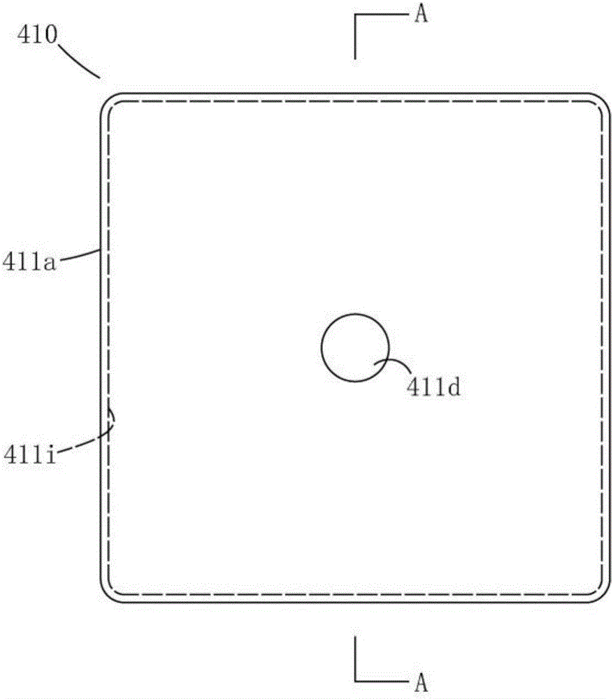
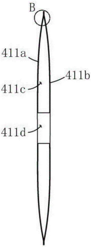
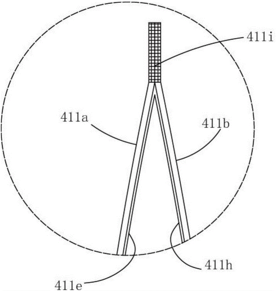
[0026] Such as Figure 1-3 As shown, the membrane filtration unit 410 includes an upper filter membrane 411a, a lower filter membrane 411b, an upper support net 411e for supporting the upper filter membrane 411a and a lower support net 411h for supporting the lower filter membrane 411b, the upper support net 411e and the lower support net 411b. A cavity 411c is formed between the support nets 411h, and the center of the membrane filtration unit 410 is provided with an installation through hole 411d passing through the upper filter membrane 411a, the upper support net 411e, the lower filter membrane 411b and the lower support net 411h. The outer edges of the upper filter membrane 411a, the lower filter membrane 411b, the upper support net 411e and the lower support net 411h are superimposed and welded to form a closed perimeter 411i, and the width of the closed perimeter 411i is 5mm. The upper support net 411e and the lower support net 411h are stainless steel screens with a me...

Embodiment 2

[0029] Such as Figure 5-8As shown, the membrane filtration unit 410 includes an upper filter membrane 411a, a lower filter membrane 411b, an upper support net 411e for supporting the upper filter membrane 411a and a lower support net 411h for supporting the lower filter membrane 411b, the upper support net 411e and the lower support net 411b. A cavity 411c is formed between the support nets 411h, and the center of the membrane filtration unit 410 is provided with an installation through hole 411d passing through the upper filter membrane 411a, the upper support net 411e, the lower filter membrane 411b and the lower support net 411h. The outer edges of the upper filter membrane 411a, the lower filter membrane 411b, the upper support net 411e and the lower support net 411h are superimposed and welded to form a closed perimeter 411i, and the width of the closed perimeter 411i is 30mm. The upper support net 411e and the lower support net 411h are stainless steel screens with a me...

Embodiment 3

[0032] Compared with Embodiment 2, the membrane filtration unit of this embodiment has the following differences: the width of the closed periphery 411i is 55mm; the upper support net 411e and the lower support net 411h are stainless steel screens with a mesh size of 40 mesh and a thickness of 2mm; the thickness of the support plate 411f is 0.3mm.


PUM

PropertyMeasurementUnit
widthaaaaaaaaaa
thicknessaaaaaaaaaa
thicknessaaaaaaaaaa

Abstract

The invention discloses a membrane filtration unit and a membrane assembly. The membrane filtration unit comprises an upper filtration membrane and a lower filtration membrane, wherein outer side edges of the upper filtration membrane and outer side edges of the lower filtration membrane are combined into closed peripheries; a mounting through hole penetrating through the upper filtration membrane and the lower filtration membrane is formed in the center of the membrane filtration unit; the membrane filtration unit further comprises an upper support net used for supporting the upper filtration membrane and a lower support net used for supporting the lower filtration membrane, the upper support net and the lower support net are arranged between the upper filtration membrane and the lower filtration membrane, and a cavity is formed between the upper support net and the lower support net. Firstly, guide channels can be formed by the support nets in the surfaces of the filtration membranes, can have a guide function and further can prevent adhesion of the upper filtration membrane and the lower filtration membrane to a certain extent; secondly, during larger water flow disturbance, the swinging amplitude of the membrane filtration unit can also be substantially reduced, and adjacent filtration membranes of adjacent membrane filtration units don't easily adhere to each other; moreover, the cavity with a stable size is formed between the upper support net and the lower support net, filtration pressure difference can be remarkably reduced, and the filtration efficiency can be improved.

Description

technical field [0001] The invention relates to the technical field of water treatment equipment, in particular to a membrane filtration unit and a membrane module using the membrane filtration unit. Background technique [0002] Membrane technology, known as the water treatment technology of the 21st century, has developed rapidly in the past 40 years. Compared with traditional water treatment technology, membrane technology has the advantages of energy saving, less investment, easy operation and high treatment efficiency, and its application has brought huge environmental and economic benefits to human beings. Membrane technology has a wide range of applications in water treatment, both for drinking water treatment and wastewater treatment, and also involved in water treatment in some special industries. [0003] In the application process of membrane technology, especially in the application of membrane stacks with stacked membranes, the distance between membranes cannot...

Claims


Application Information

Patent Timeline
Patent Type & Authority Applications(China)
IPC IPC(8): B01D63/08B01D69/10C02F1/44
CPCB01D63/08B01D69/10C02F1/44B01D2317/06B01D2313/06
Inventor 宋岱峰韩亮
Owner CHENGDU MEIFUTE MEMBRANE TECHNOLOGY CO LTD
Why Eureka
Try Eureka