Novel stirring kettle with stirring shaft capable of being conveniently replaced

A technology for convenient replacement and stirring shafts, applied to mixers with rotating stirring devices, mixer accessories, chemical instruments and methods, etc., can solve problems such as time-consuming, labor-intensive, breakage, and affecting mixing efficiency, and achieve simple structure and high efficiency , Improve the effect of stirring efficiency

Inactive Publication Date: 2017-02-22
南京途酷信息科技有限公司
View PDF6 Cites 6 Cited by
  • Summary
  • Abstract
  • Description
  • Claims
  • Application Information

AI Technical Summary

Problems solved by technology

[0003] At present, the diameter of the existing stirring blades is generally welded to the stirring shaft. During the long-term stirring process, the stirring blades are subjected to a large force and are prone to breakage, which affects the stirring efficiency. Therefore, it is necessary to take out the stirring shaft from time to time. For maintenance and replacement of the paddle, the stirring shaft needs to be separated from the motor, which is difficult to replace. At the same time, the concentricity of the stirring shaft and the motor needs to be considered after installation, which is time-consuming and laborious

Method used


Image

  • Novel stirring kettle with stirring shaft capable of being conveniently replaced
  • Novel stirring kettle with stirring shaft capable of being conveniently replaced
  • Novel stirring kettle with stirring shaft capable of being conveniently replaced

Examples


Embodiment Construction

[0019] The present invention will be further explained below in conjunction with the accompanying drawings and specific embodiments. It should be understood that the following specific embodiments are only used to illustrate the present invention and are not intended to limit the scope of the present invention.

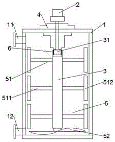
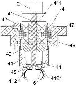
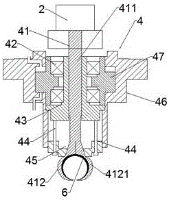
[0020] Such as Figure 1-3 As shown, a new type of stirring tank that is convenient to replace the stirring shaft includes a stirring tank 1, a motor 2, a stirring shaft 3 and a clamping device 4, the stirring shaft 3 is set at the center of the stirring tank 1, and the top is set at the center of the top of the stirring tank 1 The clamping device 4 is clamped, and the stirring shaft 3 is provided with a stirring paddle 5. The clamping device 4 includes a chuck 41, a bearing 42, a push sleeve 43, a guide rod 44, a locking plate 45, a cylinder 46 and a The piston 47 in 46, the collet 41 includes a rotating rod 411 and a clamping part 412 connected to the lower end of t...


PUM


Abstract

The invention provides a novel stirring kettle with a stirring shaft capable of being conveniently replaced. The novel stirring kettle comprises a stirring kettle body, wherein the stirring shaft is arranged in the center of the stirring kettle body; the top end is tightly clamped by a clamping device; in addition, a stirring paddle is arranged on the stirring shaft; the clamping device comprises a clamp head, a bearing, a push sleeve, a guide rod, a locking plate, an air cylinder and a piston; the clamp head comprises a clamping part formed by a rotating rod and two clamp heads; each clamping head is a circular arc plate with the semicircular cross section; the outer side of the end part connected with the rotating rod is a conical surface; a through hole matched with the rotating rod is formed in the push sleeve; inner cone holes matched with the outer conical surfaces of the clamping heads are formed in the locking plate; the rotating rod is connected into the through hole of the push sleeve in a penetrating way; the clamping part is arranged in the inner cone hole of the locking plate; the guide rod is arranged on the push sleeve. The novel stirring kettle has the advantages that the problem of high replacing difficulty of the stirring shaft is solved; the problem that whether the stirring shaft and a motor are concentric or not does not need to be considered; the stirring paddle realizes the vertical convection of the materials; the materials attached onto the inner wall of the stirring kettle can be effectively stirred and scraped; the stirring efficiency is improved.

Description

technical field [0001] The invention relates to the technical field of circuit board clamping, in particular to a circuit board processing and clamping device. Background technique [0002] Stirring kettle is a kind of shaft with blades that rotates in a cylinder or a tank to stir and mix various raw materials. It is a fluid mechanical product with a wide range of applications and a wide variety. It is suitable for the fields of chemical industry, metallurgy, medicine, food and feed, etc. . Stirring operation is an important part of the industrial reaction process. Its principle involves various processes such as fluid mechanics, heat transfer, mass transfer and chemical reaction, and the agitator is to input mechanical energy to the stirring medium to obtain a suitable flow field. device. [0003] At present, the diameter of the existing stirring blades is generally welded to the stirring shaft. During the long-term stirring process, the stirring blades are subjected to a...

Claims


Application Information

Patent Timeline
Patent Type & Authority Applications(China)
IPC IPC(8): B01F7/16B01F15/00
CPCB01F27/074B01F27/211B01F27/2121B01F27/192B01F27/80B01F35/00B01F35/31B01F35/10
Inventor 黄超超
Owner 南京途酷信息科技有限公司
Why Eureka
Try Eureka