
Drilling device with drill capable of automatically detecting and tracking center of suture needle end

An automatic detection and drilling device technology, applied in the direction of boring/drilling, drilling/drilling equipment, boring machine/drilling machine parts, etc., can solve the problems of low accuracy, high hardware cost, large measurement error, etc. , to achieve the effects of improving machining accuracy, meeting process requirements, and improving speed and accuracy

Inactive Publication Date: 2017-02-22
JIANGSU VOCATION & TECHNICAL COLLEGE OF FINANCE & ECONOMICS
View PDF6 Cites 2 Cited by
  • Summary
  • Abstract
  • Description
  • Claims
  • Application Information

AI Technical Summary

Problems solved by technology

[0003] The processing of the microholes of the needle tail of the existing medical suture needles with thread is generally done by manual adjustment, and the drill bit is roughly aligned with the axis of the needle tail, and the position of the drill bit and the fixture is kept relatively fixed for mass production. The positions of the clamped suture needles are inconsistent, and the drill bit may deviate from the center of the needle tail, resulting in low yield and low accuracy, and cannot be detected and corrected in time
There are also some devices that use laser drilling, and use methods such as triangular ranging, infrared ranging, and ultrasonic ranging, but these methods have disadvantages such as large measurement errors, high hardware costs, and large system vibration impacts.

Method used


Image

  • Drilling device with drill capable of automatically detecting and tracking center of suture needle end
  • Drilling device with drill capable of automatically detecting and tracking center of suture needle end
  • Drilling device with drill capable of automatically detecting and tracking center of suture needle end

Examples


Embodiment Construction

[0025] The technical solutions of the present invention will be described in detail below with reference to the accompanying drawings.

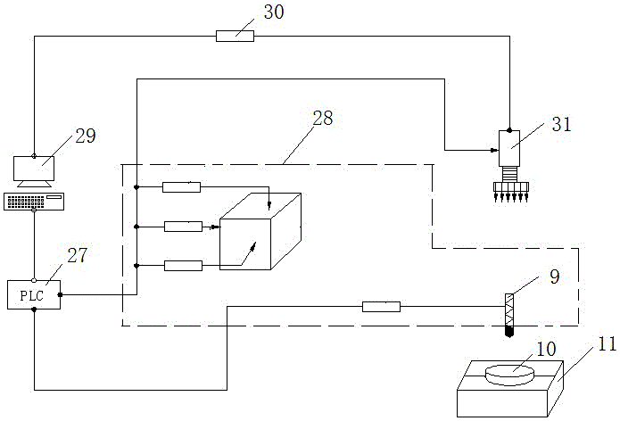
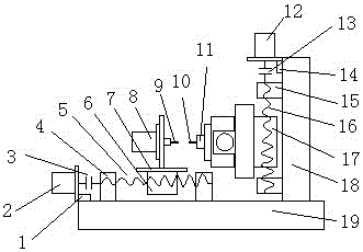
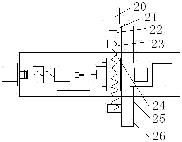
[0026] like figure 1 As shown, it includes a PLC27, a drilling mechanism 28, a computer 29, a CCD sensor 30, a camera 31 and a fixture 11; the fixture 11 clamps the suture needle to be drilled, and the camera 31 is positioned and installed on the X-axis and Y-axis of the fixture respectively , is used to photograph the suture needle tail and the drill bit being held; the camera 31 transmits the photographed picture to the computer 29 through the CCD sensor 30, and the computer 29 is equipped with an image processing program module to process the image information transmitted by the camera, The position of the center of the needle tail and the position of the drill bit are determined through algorithm analysis, and the adjustment command of the drilling mechanism 28 is issued through communication with the PLC 27 .

[0027] The cameras 31 all...


PUM


Abstract

The invention discloses a drilling device with a drill capable of automatically detecting and tracking the center of a suture needle end. The drilling device comprises a programmable logic controller (PLC), a drilling mechanism, a computer, a charge coupled device (CCD) sensor, cameras and a clamp. The clamp clamps a suture needle to be drilled, the cameras are positioned and installed on the X-axis and the Y-axis of the suture needle to be used for shooting the needle end of the clamped suture needle and the drill; the cameras transmit shot pictures to the computer through the CCD sensor, and a picture processing program module is installed in the computer and used for processing picture information sent by the cameras, the position of the needle tail circle center and the position of the drill are determined by algorithm analysis, and by communication with the PLC, an instruction for adjusting the drilling mechanism is sent out. According to the drilling device, by applying a machine vision technology, the automatic detection and tracking of the circle center are performed through picture processing by the computer, the punching center problem is solved, and the drilling device is high in automation degree and good in punching quality, reduces defective rate and is low in cost, high in efficiency and quick in speed.

Description

technical field [0001] The invention relates to a drilling device, in particular to a drilling device with a drill bit automatically detecting and tracking the center of a suture needle tail. Background technique [0002] In the process of drilling the tail of the medical suture needle, in order to ensure that the hole is punched in the center of the tail, the center of the circle of the needle tail needs to be pre-identified before drilling, which is to ensure that the drill bit and the needle maintain coaxiality during drilling. The key is to ensure the size requirements of the hole and the key to ensure the accuracy of the product. [0003] The processing of the micro-holes in the needle tail of the existing medical suture needle with thread is generally performed by manual debugging, roughly aligning the drill bit with the axis of the needle tail, and keeping the position of the drill bit and the fixture relatively fixed for mass production. The position of the suture n...

Claims


Application Information

Patent Timeline
IPC IPC(8): B23B41/00B23B49/00
CPCB23B41/00B23B49/00
Inventor 杨怀林夏建春林伟周忠旺
Owner JIANGSU VOCATION & TECHNICAL COLLEGE OF FINANCE & ECONOMICS
Learn More