General roof bend beam clamp used or laser cutting technology

A technology of laser cutting and bending beams, which is applied in the direction of manufacturing tools, laser welding equipment, welding/cutting auxiliary equipment, etc., can solve the problems of excessive extrusion of bending beams, affect the accuracy of laser cutting processing, and high cost, so as to improve precision and expand The effect of application flexibility and versatility

Active Publication Date: 2017-02-22
CRRC CHANGCHUN RAILWAY VEHICLES CO LTD
View PDF7 Cites 8 Cited by
  • Summary
  • Abstract
  • Description
  • Claims
  • Application Information

AI Technical Summary

Problems solved by technology

[0005] In order to solve the problem of poor versatility, high cost, and poor feasibility of the existing design schemes for making hat-shaped curved beam special fixtures, channel-shaped curved beam special fixtures, and hexagonal curved beam special fixtures, the traditional Horizontal arrangement of multiple sets of push-pull quick clamps in the direction of the normal line. The positioning method of the side wall of the curved beam is easy to cause excessive extrusion and deformation of the curved beam to be processed, which affects the processing accuracy of laser cutting. The technical problem of the roof curved beam universal fixture, the invention provides a kind of roof curved beam universal fixture for laser cutting process

Method used


Image

  • General roof bend beam clamp used or laser cutting technology
  • General roof bend beam clamp used or laser cutting technology
  • General roof bend beam clamp used or laser cutting technology

Examples


Embodiment Construction

[0045] The present invention will be described in further detail below in conjunction with the accompanying drawings.

[0046] Such as Figure 8 to Figure 21 As shown, the universal fixture for the roof curved beam used in the laser cutting process of the present invention includes a curved beam outer arc surface limit mechanism 8, an end plate center support 5, two end plate side supports 4, and three transverse top supports. Tightening mechanism 6, curved beam support rail 7, six connecting plates 9 and base 10, curved beam outer arc surface limit mechanism 8 includes an arc plate 8-1, and the arc of the inner wall of arc plate 8-1 The curved surface is exactly the same as the outer arc curved surface of the roof curved beam, which is used to limit the outer arc curved surface of the roof curved beam. The center support 5 of the end plate and the side supports 4 of the two end plates are all fixedly connected to the outer end surface of the arc plate 8-1, and all three of t...


PUM


Abstract

The invention discloses a general roof bend beam clamp used for the laser cutting technology, and belongs to the field of a general bend beam clamp device used for a rail vehicle roof bend beam laser cutting technology. The clamp comprises a bend beam outer side circular-arc curve face limiting mechanism, an end plate center support, two end plate side square supports, a plurality of transverse ejecting mechanisms, a bend beam supporting rail, a plurality of connecting plates and a base; the clamp can protect the roof bend beam outer side circular-arc curve face, and deformation of the curve face due to excessive extrusion is avoided; circular-arc limiting end faces parallel to the circular-arc curve face of the inner side wall of a circular-arc plate are arranged on two circular-arc curve face inner rib plates of the clamp and are specially used for carrying out matching and limiting on two ends of a circular-arc groove of a cap-shaped bend beam, and therefore positioning precision is improved; when the circular-arc curve face inner rib plates are not used, the circular-arc curve face inner rib plates can be detached, clamping of the roof bend beam cannot be disturbed and affected, and the application flexibility and generality of the clamp can be further expanded.

Description

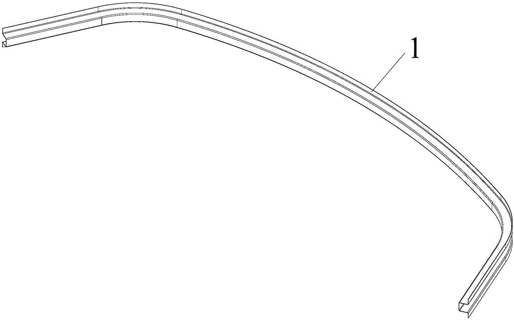
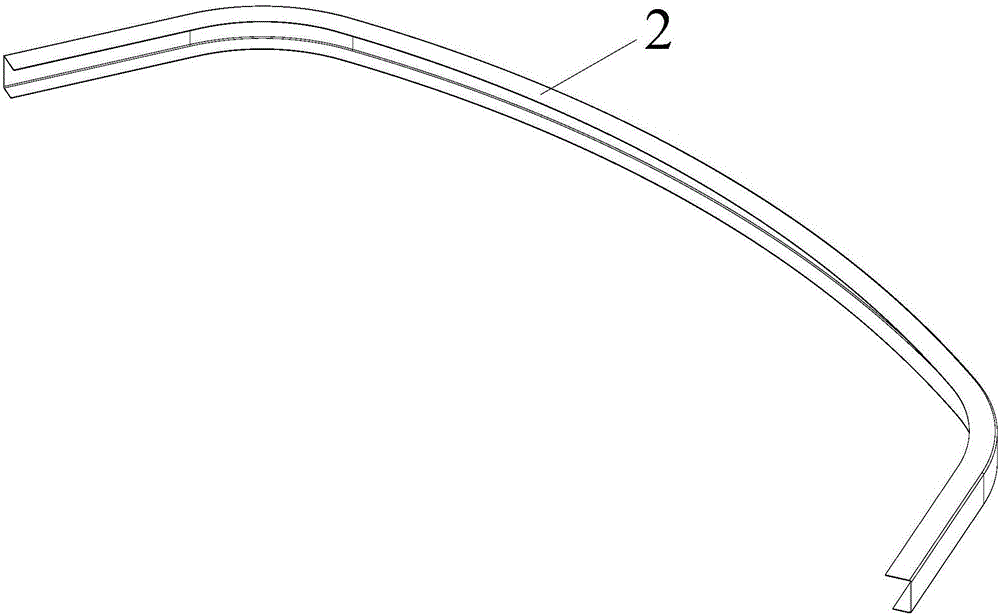
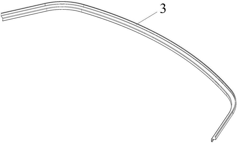
technical field [0001] The invention belongs to the field of a general-shaped curved beam clamp device used in the laser cutting process of rail vehicle roof curved beams, and in particular relates to a universal clamp for vehicle roof curved beams used in the laser cutting process. Background technique [0002] Such as Figure 4 As shown, rail vehicles such as railway passenger cars and urban railway passenger cars all use curved roof beams with basically the same span and radian. The outer end surface of the curved roof beam is called the inner arc surface of the roof curved beam, and the bottom of the largest plane in the radial direction of the roof curved beam is called the lower end surface of the roof curved beam. In addition, a small straight line is symmetrically arranged at both ends of the curved beam section part. Before performing three-dimensional beam laser cutting on the curved roof beams of such rail vehicles, it is necessary to accurately position the curv...

Claims


Application Information

Patent Timeline
Patent Type & Authority Applications(China)
IPC IPC(8): B23K26/70B23K37/04
CPCB23K26/702B23K37/04B23K2101/006
Inventor 庞春玲赵亚夫王俊元
Owner CRRC CHANGCHUN RAILWAY VEHICLES CO LTD
Why Eureka
Try Eureka