
Piston and piston copper sleeve installation method and installation equipment

A technology for installing equipment and installation methods, which is applied to pistons, mechanical equipment, metal processing equipment, etc., can solve problems such as damage to cylinder liner, copper liner falling off, and scrapping of cylinder engine, so as to achieve convenient and accurate installation, unique structure, and simple structure. Effect

Active Publication Date: 2018-08-31
强哲菲
View PDF6 Cites 0 Cited by
  • Summary
  • Abstract
  • Description
  • Claims
  • Application Information

AI Technical Summary

Problems solved by technology

[0004] The existing technology of inserting copper bushings in the piston pin seat holes, whether it is assembled by hot-fitting or cold-fitting, has greatly improved the bearing capacity of the pin holes. The risk always exists. Major failure modes such as the copper sleeve falling off towards the cylinder liner, damage to the cylinder liner and the cylinder block, causing the engine to be scrapped, are difficult to completely eliminate

Method used


Image

  • Piston and piston copper sleeve installation method and installation equipment
  • Piston and piston copper sleeve installation method and installation equipment
  • Piston and piston copper sleeve installation method and installation equipment

Examples


Embodiment Construction

[0039] The present invention will be further described in detail below in conjunction with the accompanying drawings and specific embodiments.

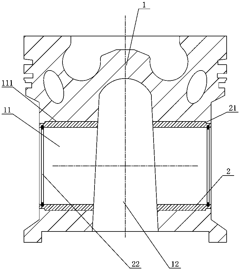
[0040] Such as figure 1 As shown, the embodiment of the piston of the present invention, the piston includes a piston body 1 and a copper sleeve 2, the pin seat of the piston body 1 is provided with a pin seat hole 11 penetrating, and a pin seat opening is provided between the two pin seat holes 11. Crotch 12, the outer circle of copper sleeve 2 is provided with card table 21, and pin seat hole 11 is provided with card groove 111 near pin seat opening crotch 12, and copper sleeve 2 is inserted into pin seat hole 11 after pin seat opening crotch 12 ends The card table 21 is engaged with the card slot 111 , and the outer circle of the copper sleeve 2 is in interference fit with the inner wall of the pin seat hole 11 . In this structure, through the engagement of the card table 21 and the card groove 111, the pin seat hole 11 itself can...


PUM


Abstract

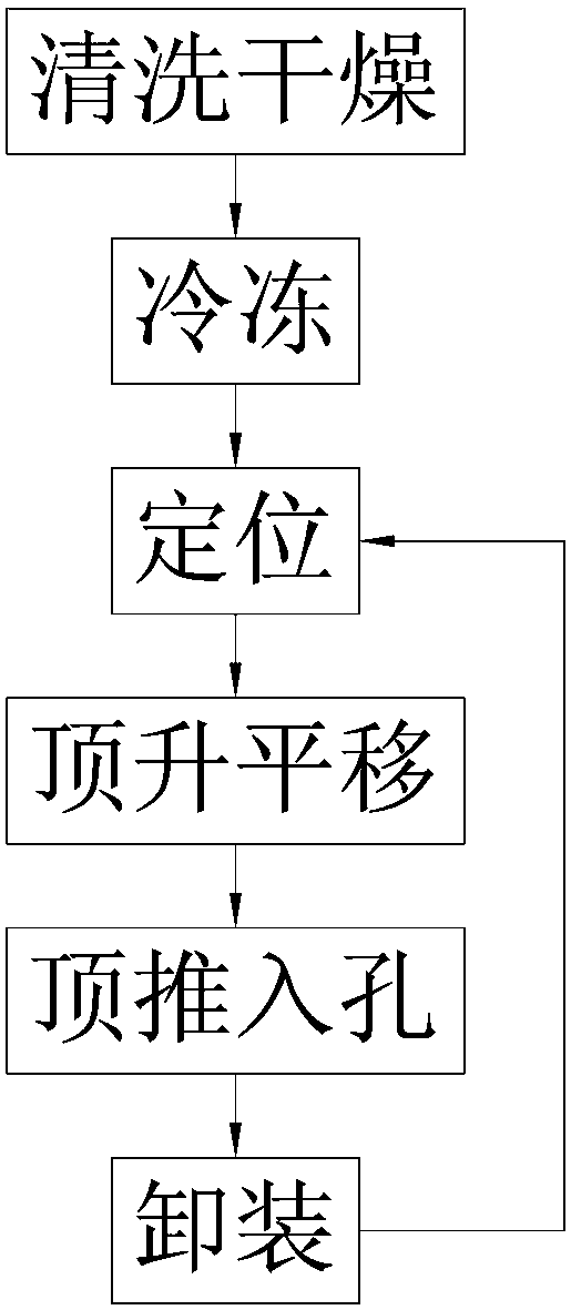
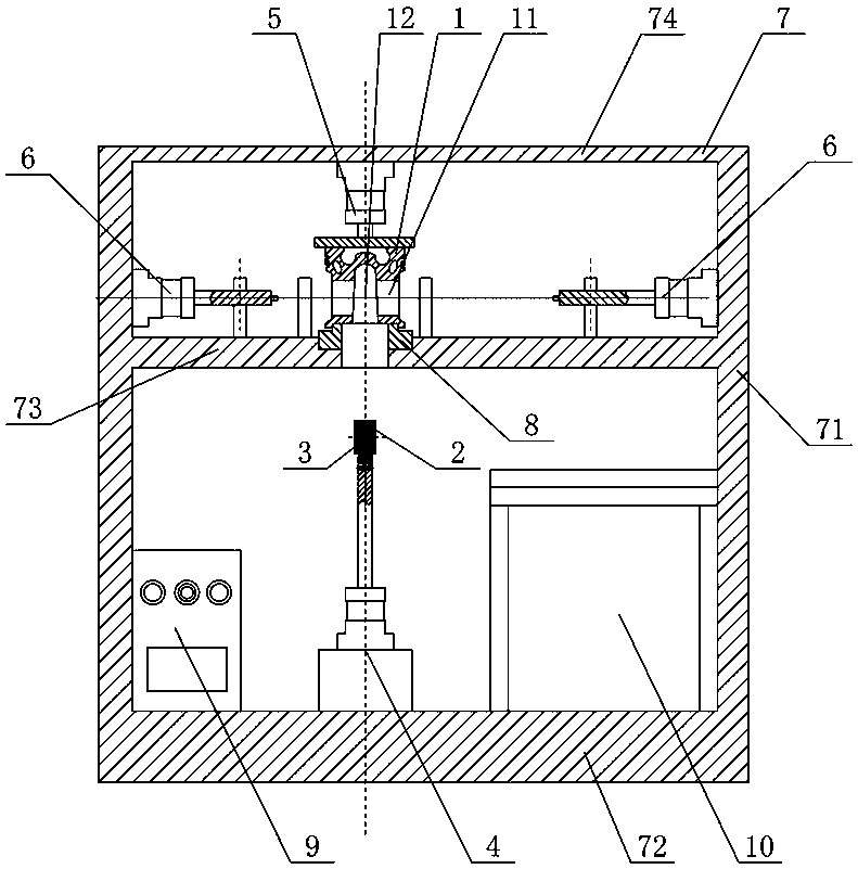
The invention relates to a piston, and a piston copper bush installation method and installation device. The piston includes a piston body and a copper bush; pin boss holes and a pin boss crotch are formed in the piston body; clamping bosses are arranged on the copper bush; clamping grooves are formed in the pin boss holes; the clamping bosses and the clamping grooves are snapped onto each other; and the copper bush and the pin boss holes form an interference fit. The installation method includes: S1, performing cleaning and drying; S2, performing freezing; S3, performing positioning; S4, performing jacking and translating; S5, jacking the copper bush into a corresponding pin boss hole; S6: performing demounting; and S7: keeping a circulation from the step S3 to the step S6. The installation device includes a copper bush clamp, a copper bush positioning jacking member, a piston positioning member, copper bush pushing members and a rack; the rack includes two side plates, a bottom plate, an intermediate plate and a top plate; the piston positioning member is connected to the top plate; a stopping disc is arranged in the intermediate plate; the copper bush positioning jacking member is connected to the bottom plate; the copper bush clamp is positioned on the top of the copper bush positioning jacking member; and the copper bush pushing members are connected to the two side plates respectively. The installation device is unique, simple and reliable in structure, and can effectively eliminate failure risk due to falling of copper bushes.

Description

technical field [0001] The invention mainly relates to the technical field of internal combustion engines, in particular to an installation method and installation equipment for a piston and a piston copper sleeve. Background technique [0002] The piston is an important part of the internal combustion engine, and it is subjected to high temperature and high pressure and repeated alternating mechanical and thermal loads in the working process. With the continuous improvement of engine power, higher requirements are put forward for the wear resistance and bearing capacity of the piston pin hole. At present, many domestic diesel engine pistons use interference fit to inlay copper sleeves in the piston pin seat hole to improve the piston. The wear resistance and load-bearing capacity of the pin hole prevents engine failure caused by cracking of the pin seat. [0003] The method of inserting the copper sleeve in the hole of the piston pin seat is to heat the piston by the hot-l...

Claims


Application Information

Patent Timeline
Patent Type & Authority Patents(China)
IPC IPC(8): B23P11/02F02F3/00
CPCB23P11/025F02F3/00
Inventor 强哲菲
Owner 强哲菲
Learn More