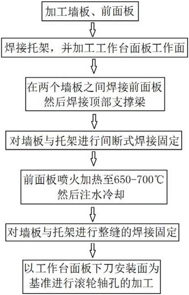
Machining process of large hydraulic plate shear rack
A processing technology and hydraulic shearing technology, used in metal processing equipment, accessories of shearing machines, shearing devices, etc., can solve problems such as difficult to control precision and easy deformation, eliminate deformation and dislocation, improve welding quality, and ensure position. The effect of precision
- Summary
- Abstract
- Description
- Claims
- Application Information
AI Technical Summary
Problems solved by technology
Method used
Image
Examples
Embodiment 1
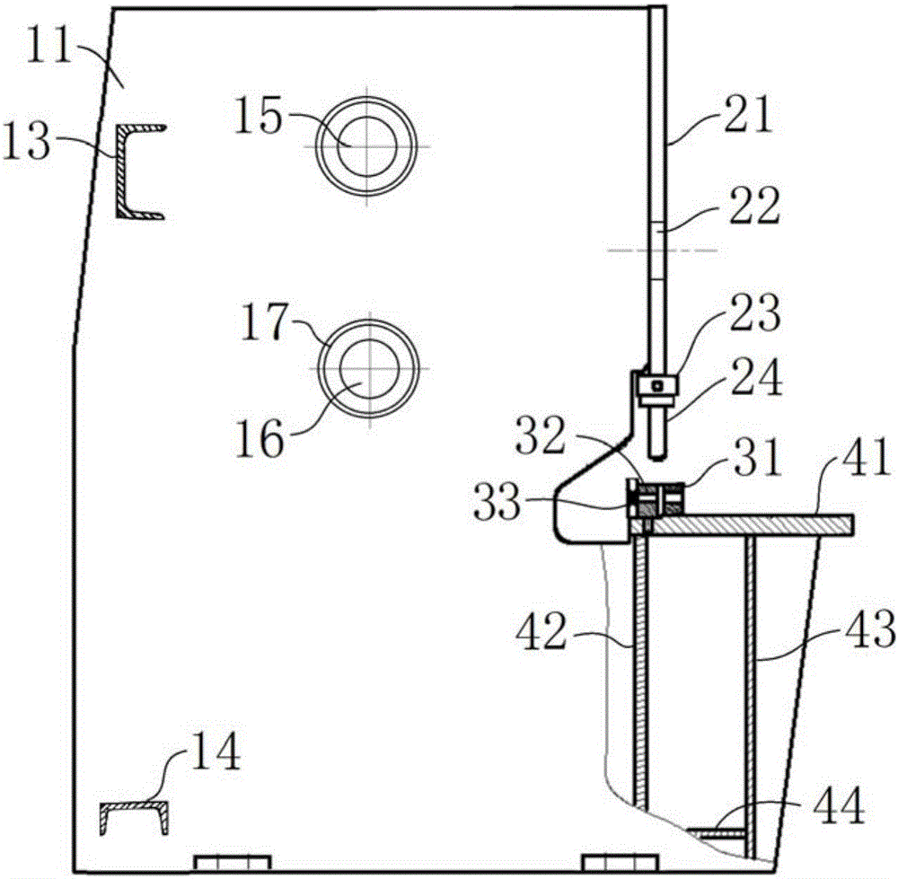
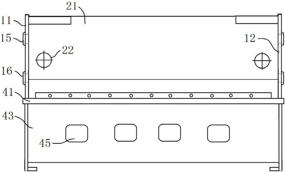
[0048] combine figure 2 , image 3 , the hydraulic press shearing machine includes a first wall panel 11 and a second wall panel 12, a front panel 21, a bracket with a worktable panel 41, and the first wall panel 11 and the second wall panel 12 are distributed on two sides of the frame The side plays the main supporting role, and the first and second are only for the convenience of distinguishing and describing, and there is no specific limitation on the actual structure of the shearing machine. The front panel 21 is positioned at the front side of the frame, and the binder seat 23 below the front panel 21 is used to fix the binder mechanism 24, which is connected to the binder seat 23 by bolts to hold down the plate when shearing. The rear side of the frame is provided with a top support beam 13, which can further improve the structural strength of the frame.
[0049] For hydraulic shearing machines, deformation will inevitably occur during welding processing. Due to the s...
Embodiment 2
[0081]The processing technology of a large-scale hydraulic shearing machine frame of this embodiment is the same as that of embodiment 1, and the difference is that the outer surface of the wallboard in step 1 corresponds to the upper roller shaft hole 15 and the lower roller shaft hole 15. A thickened plate 17 is welded at the position of the roller shaft hole 16, and the thickened plate 17 is circular and arranged coaxially with the roller shaft hole. Since the wallboards on both sides of the small shearing machine are relatively thin, the welded thickening plate 17 helps to improve the structural strength, and facilitates the overall machining operation in step 8.
[0082] After the top support beam 13 is welded in step 4, a rear ejector rod 14 is welded between the two wall panels, and the rear ejector rod 14 is located at the bottom of the wall panels to further increase the structural strength.
[0083] The flame heating temperature in step 6 is 700°C, and then it can be...
Embodiment 3
[0086] The processing technology of a frame of a large hydraulic shearing machine in this embodiment is basically the same as that of Embodiment 2, further: the welding of the entire weld seam is carried out by adopting a diagonal welding method. When welding, weld from bottom to top, and the welding sequence is the same as the intermittent welding sequence, that is: first weld the junction of the main support plate 42 and the first wall panel 11, and then perform welding on the junction of the auxiliary support plate 43 and the second wall panel 12. Welding, and then welding the junction of the main support plate 42 and the second wallboard 12 , and finally welding the junction of the auxiliary support plate 43 and the first wallboard 11 .
[0087] In combination with the above embodiments, the present invention first rationally arranges the welding process, assembles the frame frame, and then uses the method of spraying fire to eliminate welding deformation; finally uses the ...
PUM
 Abstract
Description
Claims
Application Information
 - R&D
- Intellectual Property
- Life Sciences
- Materials
- Tech Scout
- Unparalleled Data Quality
- Higher Quality Content
- 60% Fewer Hallucinations
Browse by: Latest US Patents, China's latest patents, Technical Efficacy Thesaurus, Application Domain, Technology Topic, Popular Technical Reports.
© 2025 PatSnap. All rights reserved.Legal|Privacy policy|Modern Slavery Act Transparency Statement|Sitemap|About US| Contact US: help@patsnap.com


