
Y-shaped blade shot blaster

A shot blasting machine and blade technology, used in rotor blades, impellers, grinding/polishing equipment, etc., can solve problems such as chatter, impact on service life, shot blasting quality, blade thickness, etc.

Inactive Publication Date: 2017-02-22
UNIV OF JINAN
View PDF11 Cites 6 Cited by
  • Summary
  • Abstract
  • Description
  • Claims
  • Application Information

AI Technical Summary

Problems solved by technology

Typically, such as the Chinese patent document CN202640171U, which discloses an impeller blade used in a shot blasting machine, the blade used is a curved blade (generally called a forward curved blade), and the stiffness of this type of blade itself depends on the In addition, it is also related to its own thickness, but due to the influence of its installation space, it is not easy to make the blade too thick, and its service life mainly depends on the use of special materials, such as high manganese alloy, resulting in high cost
Its working mode is single, using the outer arc surface of its arc-shaped blade as the working surface, based on the structural view provided by it, it can be determined that its rotation can only be counterclockwise
[0005] And as the used blade of Chinese patent document CN103600300A is arc-shaped blade equally, but the installation mode of its blade is opposite to the installation mode of Chinese patent document CN202640171U, also can only realize clockwise rotation
The installation method of this type of blade is generally that the side of the blade is installed on the end plate of the impeller, such as the Chinese patent document CN202640171U, which relies on one-sided fixing of the dovetail groove. Under this fixing condition, the supporting forces on both sides of the blade are different. prone to leaf deformation
[0006] Chinese patent document CN204639939U discloses a fixing structure of the impeller body of the blasting machine. The fixing method is to fix the blades based on two discs, wherein the discs are located at the root of the blade, which is similar to the fixing of the root of the blade, and the blade remains There is a relatively long overhang, which is easy to vibrate during the rotation of the impeller, which affects its service life and shot blasting quality
[0007] However, Chinese patent document CN203495774U adopts an integrated shot blasting wheel. Although the integrated structure has high structural strength, the maintainability is relatively poor. Once the blade is damaged, it cannot be replaced, resulting in the scrapping of the entire impeller.

Method used


Image

  • Y-shaped blade shot blaster
  • Y-shaped blade shot blaster
  • Y-shaped blade shot blaster

Examples


Embodiment Construction

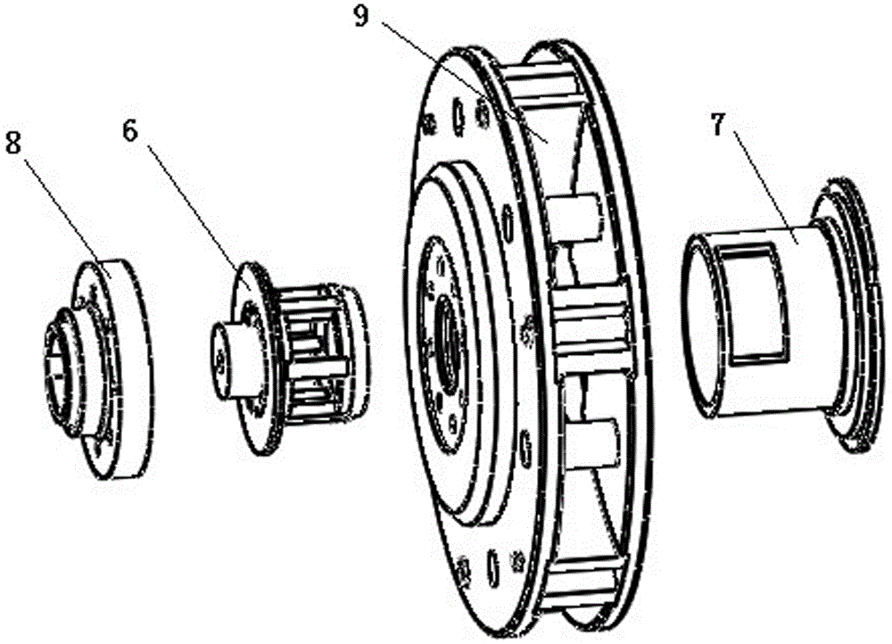
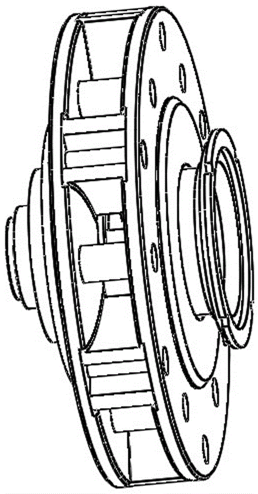
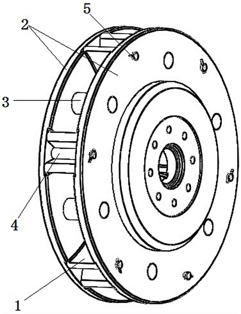
[0037] Refer to the instructions attached figure 2 with 3 As shown, the Y-blade blasting device is a typical wheel-type component, and its whole is similar to a cylinder, or an equivalent cylinder, so its end surface is essentially an axial end surface. The so-called radial is the radial under the condition of the wheel axis structure of the blade blaster as a whole.

[0038] For Y-shaped blade 1, see the manual Figure 4 , The whole is a Y-shaped block with a left-right symmetrical structure, which can also be considered as a combination of a V-shaped block and a strip-shaped block, such as Figure 4 As shown, the combined sheet body 1-3 is a whole curved surface, similar to two forward curved blades.

[0039] At the same time, in the azimuth structure, based on the wheel structure, for Figure 4 In the structure shown in the structure, the base 1-2 is constituted as the end panel part of the Y-shaped block and the strip block combination. The sheet 1-3 shown in the figure is a wo...


PUM


Abstract

The invention discloses a Y-shaped blade shot blaster. The Y-shaped blade shot blaster comprises an impeller combination with a hub hole, and a shot distributing device arranged in the hub hole and used for providing shots. The impeller combination comprises two end discs and Y-shaped blades, the inner side faces of the two end discs are opposite and are assembled into an impeller body through a hub. A plurality of Y-shaped grooves with left-right symmetric structures are formed in the corresponding inner side faces of the two end discs in an alignment manner. The heads of the Y-shaped grooves are arranged in a centripetal manner. The corresponding Y-shaped blades are positioned at the two axial ends of each end disc, the Y-shaped blades are fixed in the Y-shaped grooves formed in the two end discs, and the two outer side faces, in the circumferential direction of the impeller combination, of each Y-shaped blade are shot blasting work faces. The service life of the Y-shaped blade shot blaster is long.

Description

Technical field [0001] The invention relates to a shot blasting machine. Background technique [0002] Shot blast is a mechanical surface treatment process. Similar processes include sand blasting and shot blasting. Shot blasting is a cold treatment process, divided into shot blasting cleaning process and shot blasting strengthening process. [0003] The main structure of the shot blasting machine is the impeller body. The impeller body is generally equipped with a plurality of blades. The impeller body and the sub-blasting wheel located in the center of the shot blasting wheel are mounted on a main shaft driven by, for example, a motor. The shot-in tube is connected with the pill-distributing wheel to provide projectiles, which are then distributed by the pill-distributing wheel. With the rotation of the impeller body, the projectiles obtain the required speed. [0004] Regarding the shot blasting machine, its performance is closely related to the shape of the blade, and the shape...

Claims


Application Information

Patent Timeline
Patent Type & Authority Applications(China)
IPC IPC(8): B24C5/00B24C5/06
CPCB24C5/00B24C5/062
Inventor 王守仁徐庆东郭培全杨丽颖王高琦王砚军
Owner UNIV OF JINAN
Learn More