
Thermal cutting device for woven bags

A technology of thermal cutting and woven bags, applied in the field of plastic product manufacturing, can solve the problems of plastic thin strips detachment, low processing efficiency, disintegration of woven bags, etc., to avoid movement, improve processing efficiency, and avoid disintegration effects.

Active Publication Date: 2017-02-22
重庆淬智机械有限公司
View PDF5 Cites 2 Cited by
  • Summary
  • Abstract
  • Description
  • Claims
  • Application Information

AI Technical Summary

Problems solved by technology

The woven bag is woven by several thin plastic strips. If you cut it directly with a knife edge, the plastic thin strips will separate from each other at the cutting seam, and the woven bag may disintegrate.
In order to prevent the disintegration of the woven bag, it is also necessary to carry out thermoplastic edge sealing on the cut seam, and its processing efficiency is low

Method used


Image

  • Thermal cutting device for woven bags

Examples


Embodiment 1

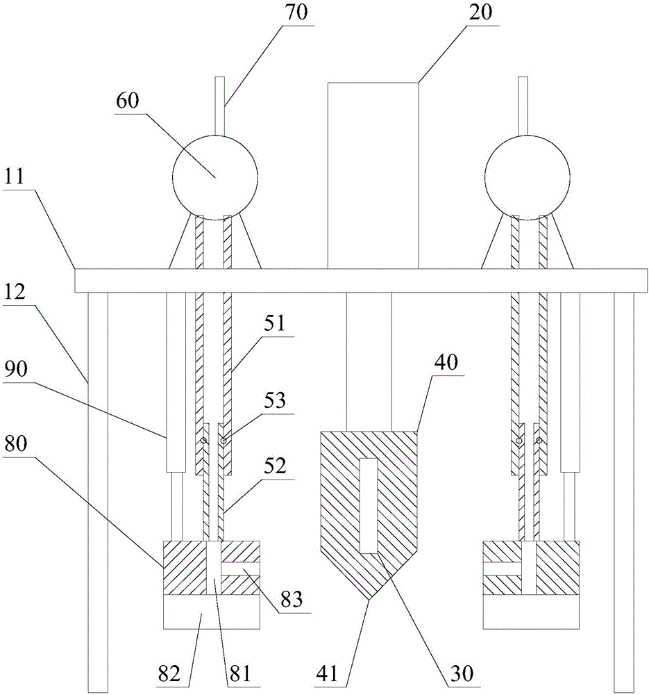
[0027] Such as figure 1 As shown, the thermal cutting equipment for woven bags includes a top plate 11, a pillar 12, a pneumatic cylinder 20, an electric heating block 30, a cutting knife 40, a first suction pipe 51, a second suction pipe 52, an air pump 60, and an exhaust Pipe 70, suction air block 80 and telescopic cylinder 90;

[0028] A plurality of the pillars 12 are vertically connected to the lower surface of the top plate 11 to support the top plate 11; the pneumatic cylinder 20 is fixed on the upper surface of the top plate 11; the piston rod of the pneumatic cylinder 20 It penetrates the top plate 11 from top to bottom and is connected to a cutting block 40 located below the top plate 11; the bottom of the cutting block 40 is provided with a cutting edge 41; the electric heating block 30 is arranged in the cutting block 40;

[0029] The air pump 60 is fixed on the top plate 11, the inlet of the air pump 60 is connected to one end of the first suction pipe 50, and the out...


PUM


Abstract

The invention discloses a thermal cutting device for woven bags. The thermal cutting device is characterized in that a plurality of struts are vertically connected on the lower surface of a top plate to support the top plate; a pneumatic cylinder is fixed to the upper surface of the top plate; a piston rod of the pneumatic cylinder penetrates through the top plate from top to bottom to be connected with a cutting block below the top plate; the bottom of the cutting block has a cutting edge; an electric heating block is arranged inside the cutting block; air pumps are fixed to the top plate; inlets of the air pumps are connected with one ends of first air suction pipes; outlets of the air pumps are connected with exhaust pipes; one ends of second air suction pipes are inserted into the other ends of the first air suction pipes in a sliding manner; the other ends of the second air suction pipes are connected with air suction pressing blocks; the second air suction pipes slide relative to the first air suction pipes to drive the air suction pressing blocks to move up and down; a plurality of air holes which communicate with the second air suction pipes are formed in the bottoms of the air suction pressing blocks; telescopic cylinders are fixed to the lower surface of the top plate; and piston rods of the telescopic cylinders are connected with the air suction pressing blocks. According to the thermal cutting device, exhaust gas can be sucked away, and the cutting precision can be improved.

Description

Technical field [0001] The invention relates to the field of plastic product manufacturing, in particular to a thermal cutting device for woven bags. Background technique [0002] Woven bags, also known as snakeskin bags. It is a kind of plastic used for packaging. Its raw materials are generally various chemical plastic raw materials such as polyethylene and polypropylene. In the manufacturing process of woven bags, they will be cut to obtain the right size. The woven bag is woven from several thin plastic strips. If it is cut directly with a knife, the thin plastic strips at the cutting seam will separate from each other, and the woven bag may disintegrate. In order to prevent the disintegration of the woven bag, it is also necessary to perform thermoplastic edge sealing at the cut seam, which has low processing efficiency. Summary of the invention [0003] The purpose of the present invention is to overcome the above-mentioned problems of the prior art and provide a thermal ...

Claims


Application Information

Patent Timeline
Patent Type & Authority Applications(China)
IPC IPC(8): B31B70/14B31B70/74
Inventor 陈和平
Owner 重庆淬智机械有限公司
Learn More