Hybrid power driving system and vehicle
A drive system and hybrid technology, applied in the field of vehicle engineering, can solve the problems of frequent transient response, complex structure and large mass of automobiles, so as to reduce the transient response of vehicles, flexible and changeable space layout, and improve fuel economy. Effect
- Summary
- Abstract
- Description
- Claims
- Application Information
AI Technical Summary
Problems solved by technology
Method used
Image
Examples
Embodiment 1
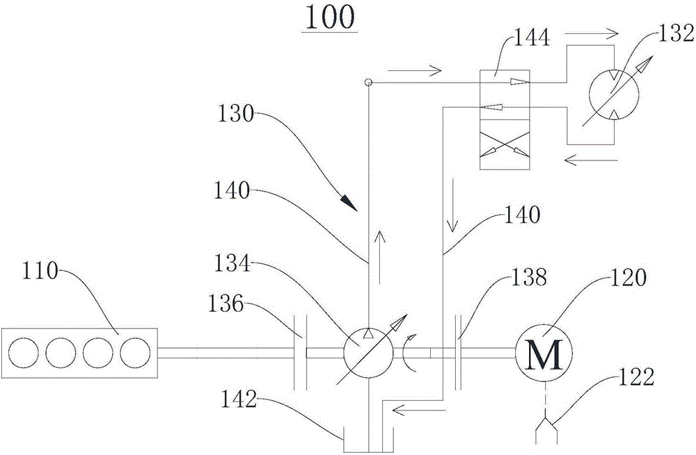
[0021] Please refer to figure 1 , the present embodiment provides a hybrid drive system 100 , which includes an engine 110 , an electric motor 120 and a hydraulic assembly 130 . The hydraulic assembly 130 is connected to the engine 110 and the electric motor 120 respectively.
[0022] The hydraulic assembly 130 includes a hydraulic motor 132 and a hydraulic pump 134 . The hydraulic pump 134 is connected to the engine 110 through a first clutch 136 , and the hydraulic pump 134 is connected to the electric motor 120 through a second clutch 138 . The hydraulic pump 134 is connected to the hydraulic motor 132 through the pipeline 140, and drives the rotor (not shown) of the hydraulic motor 132 to rotate through hydraulic transmission. Hydraulic oil (not shown in the figure) is sucked out from the oil tank 142 by the hydraulic pump 134, then passed into the hydraulic motor 132 through the delivery channel of the pipeline 140, finally flows out by the hydraulic motor 132, and retu...
Embodiment 2
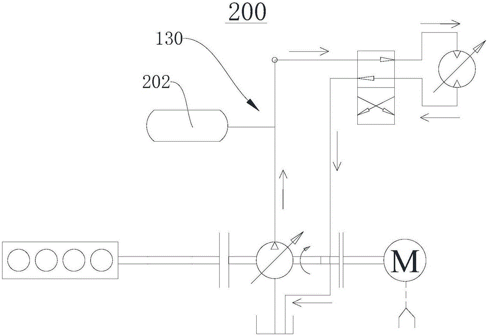
[0034] Please refer to figure 2 , this embodiment provides a hybrid drive system 200 , which is substantially the same as the hybrid drive system 100 in Embodiment 1, the main difference between the two is that the hydraulic assembly 130 of this embodiment further includes a hydraulic accumulator 202 .
[0035] please refer again figure 1 , the hydraulic accumulator 202 is connected to the hydraulic pump 134 through the pipeline 140 . The hydraulic accumulator 202 may be one of various accumulators such as a spring type accumulator, a gas isolation type accumulator (gas cylinder type, piston type, bladder type) and the like. The hydraulic accumulator 202 can absorb the excess high-pressure hydraulic oil output by the hydraulic pump 134 when the rotor of the hydraulic motor 132 decelerates and brakes, and recovers braking energy. Effect of hydraulic shocks and pressure pulsations.
[0036] The difference in working principle between the hybrid drive system 200 and the hybri...
Embodiment 3
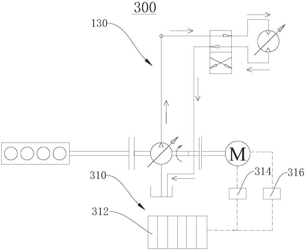
[0038] Please refer to image 3 and figure 1 , this embodiment provides a hybrid drive system 300, which is substantially the same as the hybrid drive system 100 in Embodiment 1, the main difference between the two is that the hybrid drive system 300 of this embodiment also includes a power storage component 310, which stores Electrical assembly 310 includes battery 312 . The motor 120 is electrically connected to the battery 312 , and when the current and voltage required by the motor 120 match the current and voltage provided by the battery 312 , the battery 312 can directly supply power to the motor 120 . The storage battery 312 can be replaced to ensure sufficient power to drive the motor 120 to rotate.
[0039] Preferably, please refer to image 3 and figure 1 In order to better match the current and voltage provided by the storage battery 312 with the current and voltage required by the motor 120 , the power storage assembly 310 further includes a first converter 314...
PUM
 Abstract
Description
Claims
Application Information
 - R&D
- Intellectual Property
- Life Sciences
- Materials
- Tech Scout
- Unparalleled Data Quality
- Higher Quality Content
- 60% Fewer Hallucinations
Browse by: Latest US Patents, China's latest patents, Technical Efficacy Thesaurus, Application Domain, Technology Topic, Popular Technical Reports.
© 2025 PatSnap. All rights reserved.Legal|Privacy policy|Modern Slavery Act Transparency Statement|Sitemap|About US| Contact US: help@patsnap.com


