Eureka AIR delivers breakthrough ideas for toughest innovation challenges, trusted by R&D personnel around the world.

Efficient printing and dyeing device for cloth material

A high-efficiency, cloth-based technology, applied in the processing of textile materials, processing textile material carriers, and processing textile material containers, etc., can solve the problems of printing and dyeing agent residues that cannot be processed in time, uneven printing and dyeing, etc., and achieve improved printing and dyeing efficiency and low power consumption , the effect of high tolerance

Inactive Publication Date: 2017-02-22
绍兴明业印染有限公司
View PDF5 Cites 8 Cited by
  • Summary
  • Abstract
  • Description
  • Claims
  • Application Information

AI Technical Summary

Problems solved by technology

[0005] In order to overcome the shortcomings of the existing cloth printing and dyeing devices, such as uneven printing and dyeing, natural drying after printing and dyeing before rolling, and printing and dyeing agent residues that cannot be processed in time, the technical problem to be solved by the present invention is to provide a uniform printing and dyeing, High-efficiency printing and dyeing device for fabrics that are air-dried and do not contain printing and dyeing agent residues during the printing and dyeing process

Method used


Image

  • Efficient printing and dyeing device for cloth material
  • Efficient printing and dyeing device for cloth material
  • Efficient printing and dyeing device for cloth material

Examples


Embodiment 1

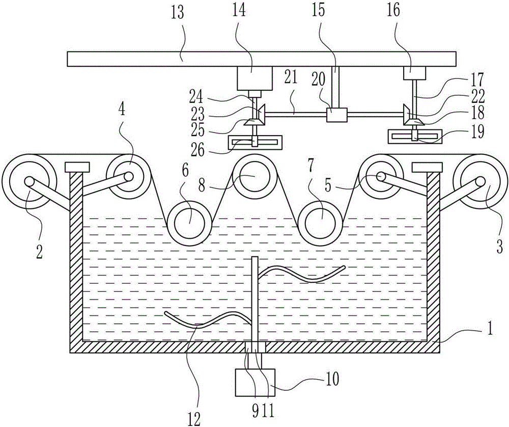
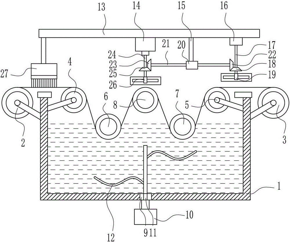
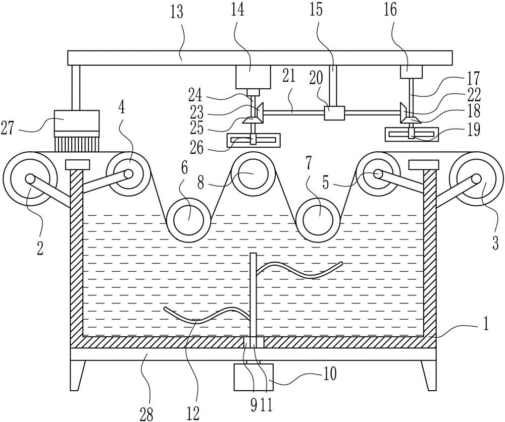
[0035] A high-efficiency printing and dyeing device for cloth, such as Figure 1-5 As shown, it includes printing and dyeing pool 1, discharge roller 2, electric receiving roller 3, left guide roller 4, right guide roller 5, first guide roller 6, second guide roller 7, upper guide roller 8, first motor 10. Rotating rod 11, stirring rod 12, top plate 13, second motor 14, guide rod 15, bearing seat 16, first rotating shaft 17, first bevel gear 18, first fan 19, guide sleeve 20, second rotating shaft 21 , the second bevel gear 22, the third bevel gear 23, the third rotating shaft 24, the fourth bevel gear 25 and the second fan 26, and the upper parts of the left and right sides of the printing and dyeing pool 1 are respectively provided with a discharge roller 2 and an electric receiving roller 3, The upper part of the left and right sides of the printing and dyeing tank 1 is respectively provided with a left guide roller 4 and a right guide roller 5, and a first guide roller 6 a...


PUM


Abstract

The invention relates to a printing and dyeing device for a cloth material, in particular to an efficient printing and dyeing device for the cloth material. The efficient printing and dyeing device for the cloth material achieves the technical purposes that printing and dyeing are uniform, air drying can be performed in the printing and dyeing process, and no printing and dyeing agent residue is contained. In order to achieve the technical purposes, the efficient printing and dyeing device for the cloth material comprises a printing and dyeing pond, a discharging roller, an electric receiving roller, a left guiding roller, a right guiding roller, a first guiding roller, a second guiding roller, an upper guiding roller, a first motor, a rotating rod and the like. The upper portions of the left and right sides of the printing and dyeing pond are provided with the discharging roller and the electric receiving roller respectively. The upper portions of the left and right sides inside the printing and dyeing pond are provided with the left guiding roller and the right guiding roller respectively. The first guiding roller and the second guiding roller are symmetrically arranged inside the printing and dyeing pond. The mode of two-time printing and dyeing is adopted, a fan is used for performing air drying on the cloth material obtained after two-time printing and dyeing, and a printing and dyeing agent is prevented from being stuck to the inner wall of the printing and dyeing pond through a stickiness removal structure.

Description

technical field [0001] The invention relates to a printing and dyeing device for cloth, in particular to a high-efficiency printing and dyeing device for cloth. Background technique [0002] Printing and dyeing is also called dyeing and finishing. It is a processing method, and it is also a general term for pretreatment, dyeing, printing, finishing, washing, etc.; the undergraduate dyeing and finishing major has now been incorporated into the light chemical engineering major; as early as the Neolithic Age six or seven thousand years ago, Our ancestors were able to dye sackcloth red with hematite powder. The primitive tribes living in the Nomuhong area of ​​the Qaidam Basin in Qinghai can dye wool into yellow, red, brown, blue and other colors, and weave woolen cloth with colored stripes. During the Shang and Zhou dynasties, dyeing technology continued to improve. There are full-time officials "dye people" in the palace handicraft workshops to "hand dye grass" and manage t...

Claims


Application Information

Patent Timeline
IPC IPC(8): D06B3/12D06B15/00D06B23/00D06B23/04D06B23/14
CPCD06B3/12D06B15/00D06B23/00D06B23/04D06B23/14
Inventor 赵明江
Owner 绍兴明业印染有限公司
Why Eureka
Eureka Blog
Learn More